Материал: 9133

Philips Semiconductors Product specification
Rectifier diodes |
|
|
|
|
|
|
|
|
|
|
|
|
|
|
|
|
|
|
BY229F series |
|
|||||||||||||||||
fast, soft-recovery |
|
|
|
|
|
|
|
|
|
|
|
|
|
|
|
|
|
|
|
|
|
|
|
|
|
|
|
|
|
|
|
||||||
|
|
|
|
|
|
|
|
|
|
|
|
|
|
|
|
|
|
|
|
|
|||||||||||||||||
GENERAL DESCRIPTION |
|
QUICK REFERENCE DATA |
|
|
|
|
|
|
|
|
|
|
|
|
|
|
|
|
|
|
|||||||||||||||||
|
|
|
|
|
|
|
|
|
|
|
|
||||||||||||||||||||||||||
Glass-passivated double diffused |
|
SYMBOL |
|
|
PARAMETER |
MAX. |
MAX. |
MAX. |
MAX. |
UNIT |
|
||||||||||||||||||||||||||
rectifier diodes in a plastic full pack |
|
|
|
|
|
|
|
|
|
|
|
|
|
|
|
|
|
|
|
|
|
|
|
|
|
|
|
|
|
|
|
||||||
|
|
|
|
|
|
|
|
|
|
BY229F |
-200 |
|
|
-400 |
|
-600 |
|
|
-800 |
|
|
|
|
|
|||||||||||||
envelope featuring low forward |
|
|
|
|
|
|
|
|
|
|
|
|
|
|
|
|
|
|
|
||||||||||||||||||
voltage drop, fast reverse recovery |
|
VRRM |
|
|
Repetitive peak reverse |
200 |
|
|
400 |
|
600 |
|
800 |
|
|
V |
|
||||||||||||||||||||
and soft recovery characteristic. The |
|
|
|
|
voltage |
|
|
|
|
|
|
|
|
|
|
|
|
|
|
|
|
|
|
||||||||||||||
devices are intended for use in TV |
|
IF(AV) |
|
|
Average forward current |
8 |
|
|
8 |
|
8 |
|
8 |
|
|
|
A |
|
|||||||||||||||||||
receivers, monitors and switched |
|
IFSM |
|
|
Non-repetitive peak |
60 |
|
|
60 |
|
60 |
|
60 |
|
|
A |
|
||||||||||||||||||||
mode power supplies. |
|
|
|
|
forward current |
|
|
|
|
|
|
|
|
|
|
|
|
|
|
|
|
|
|
||||||||||||||
|
|
|
|
|
|
|
|
trr |
|
|
Reverse recovery time |
135 |
|
|
135 |
|
135 |
|
135 |
|
|
ns |
|
||||||||||||||
PINNING - SOD100 |
|
PIN CONFIGURATION |
SYMBOL |
|
|
|
|
|
|
|
|
|
|
|
|
|
|||||||||||||||||||||
|
|
|
|
|
|
|
|
|
|
|
|
|
|
|
|
|
|
|
|
|
|
|
|
|
|
|
|
|
|
|
|
|
|
|
|
||
|
PIN |
|
DESCRIPTION |
|
|
|
|
case |
|
|
|
|
|
|
|
|
|
|
|
|
|
|
|
|
|
|
|
|
|
|
|
|
|
|
|||
|
|
|
|
|
|
|
|
|
|
|
|
|
|
|
|
|
|
|
|
|
|
|
|
|
|
|
|
|
|||||||||
|
|
|
|
|
|
|
|
|
|
|
|
|
|
|
|
|
|
|
|
|
|
|
|
|
|
|
|
|
|||||||||
|
|
|
|
|
|
|
|
|
|
|
|
|
|
|
|
|
|
|
|
|
|
|
|
|
|
|
|
|
|
|
|
|
|
|
|
||
1 |
|
|
cathode |
|
|
|
|
|
|
|
|
|
|
|
|
|
|
|
|
|
|
|
|
|
|
|
|
|
|
|
|
|
|
||||
|
|
|
|
|
|
|
|
|
|
|
|
|
|
|
|
|
|
|
a |
|
|
|
|
|
|
k |
|
|
|
||||||||
2 |
|
|
anode |
|
|
|
|
|
|
|
|
|
|
|
|
|
|
|
|
|
|
|
|
|
|
|
|
|
|
||||||||
|
|
|
|
|
|
|
|
|
|
|
|
|
|
|
|
|
|
|
|
|
|
|
|
|
|||||||||||||
|
|
|
|
|
|
|
|
|
|
|
|
|
|
|
|
|
|
|
|
|
|
|
|
|
|
|
|
|
|
|
|
|
|
||||
|
case |
|
isolated |
|
|
|
|
|
|
|
|
|
|
|
|
|
|
|
|
|
|
|
|
|
|
|
|
|
|
|
|
|
|
|
|
||
|
|
|
|
|
|
|
|
|
|
|
|
|
|
|
|
|
|
|
|
|
|
|
|
|
|
|
|
|
|
|
|
|
|
||||
|
|
|
|
|
|
|
|
|
1 |
|
2 |
|
|
|
|
|
|
|
|
|
|
|
|
|
|
|
|
|
|
|
|
|
|
|
|||
|
|
|
|
|
|
|
|
|
|
|
|
|
|
|
|
|
|
|
|
|
|
|
|
|
|
|
|
|
|
|
|
|
|
|
|
|
|
LIMITING VALUES
Limiting values in accordance with the Absolute Maximum System (IEC 134).
SYMBOL |
PARAMETER |
CONDITIONS |
MIN. |
|
MAX. |
|
UNIT |
||
|
|
|
|
|
|
|
|
|
|
|
|
|
|
-200 |
-400 |
|
-600 |
-800 |
|
VRSM |
Non-repetitive peak reverse |
|
- |
200 |
400 |
|
600 |
800 |
V |
|
voltage |
|
|
|
|
|
|
|
|
VRRM |
Repetitive peak reverse voltage |
|
- |
200 |
400 |
|
600 |
800 |
V |
VRWM |
Crest working reverse voltage |
|
- |
150 |
300 |
|
500 |
600 |
V |
VR |
Continuous reverse voltage |
|
- |
150 |
300 |
|
500 |
600 |
V |
I |
Average forward current1 |
square wave; |
- |
|
|
8 |
|
A |
|
F(AV) |
|
δ = 0.5; Ths ≤ 83 ˚C |
|
|
|
|
|
|
|
|
|
- |
|
|
7 |
|
A |
||
|
|
sinusoidal; |
|
|
|
||||
|
|
a = 1.57; |
|
|
|
|
|
|
|
IF(RMS) |
RMS forward current |
Ths ≤ 90 ˚C |
- |
|
|
11 |
|
A |
|
t = 25 μs; δ = 0.5; |
|
|
|
||||||
IFRM |
Repetitive peak forward current |
- |
|
|
16 |
|
A |
||
IFSM |
|
Ths ≤ 83 ˚C |
|
|
|
|
|
|
|
Non-repetitive peak forward |
t = 10 ms |
- |
|
|
60 |
|
A |
||
|
current. |
t = 8.3 ms |
- |
|
|
66 |
|
A |
|
|
|
sinusoidal; |
|
|
|
|
|
|
|
|
|
Tj = 150 ˚C prior to |
|
|
|
|
|
|
|
|
|
surge; with |
|
|
|
|
|
|
|
I2t |
I2t for fusing |
reapplied VRWM(max) |
- |
|
|
18 |
|
A2s |
|
t = 10 ms |
|
|
|
||||||
Tstg |
Storage temperature |
|
-40 |
|
150 |
|
˚C |
||
Tj |
Operating junction temperature |
|
- |
|
150 |
|
˚C |
||
1 Neglecting switching and reverse current losses.
October 1994 |
1 |
Rev 1.100 |

Philips Semiconductors Product specification
Rectifier diodes |
|
|
|
|
|
BY229F series |
|
|||
fast, soft-recovery |
|
|
|
|
|
|
|
|
|
|
|
|
|
|
|
|
|
|
|
|
|
ISOLATION |
|
|
|
|
|
|
|
|
|
|
Ths = 25 ˚C unless otherwise specified |
|
|
|
|
|
|
|
|
|
|
SYMBOL |
PARAMETER |
|
CONDITIONS |
|
MIN. |
|
TYP. |
MAX. |
UNIT |
|
Visol |
Repetitive peak voltage from |
|
R.H. ≤ 65% ; clean and dustfree |
|
- |
|
- |
1500 |
V |
|
|
both terminals to external |
|
|
|
|
|
|
|
|
|
|
heatsink |
|
|
|
|
|
|
|
|
|
Cisol |
Capacitance from cathode to |
|
f = 1 MHz |
|
- |
|
12 |
- |
pF |
|
|
external heatsink |
|
|
|
|
|
|
|
|
|
THERMAL RESISTANCES |
|
|
|
|
|
|
|
|
|
|
|
|
|
|
|
|
|
|
|
|
|
SYMBOL |
PARAMETER |
CONDITIONS |
MIN. |
TYP. |
MAX. |
UNIT |
|
|||
|
|
|
|
|
|
|
|
|
|
|
Rth j-hs |
Thermal resistance junction to |
with heatsink compound |
- |
|
- |
4.8 |
K/W |
|
||
|
heatsink |
without heatsink compound |
- |
|
- |
7.2 |
K/W |
|
||
Rth j-a |
Thermal resistance junction to |
in free air. |
- |
|
55 |
- |
K/W |
|
||
|
ambient |
|
|
|
|
|
|
|
|
|
STATIC CHARACTERISTICS |
|
|
|
|
|
|
|
|
|
|
Tj = 25 ˚C unless otherwise stated |
|
|
|
|
|
|
|
|
|
|
SYMBOL |
PARAMETER |
CONDITIONS |
MIN. |
TYP. |
MAX. |
UNIT |
|
|||
|
|
|
|
|
|
|
|
|
|
|
VF |
Forward voltage |
IF = 20 A |
- |
|
1.5 |
1.85 |
V |
|
||
IR |
Reverse current |
VR = VRWM; Tj = 125 ˚C |
- |
|
0.1 |
0.4 |
mA |
|
||
DYNAMIC CHARACTERISTICS |
|
|
|
|
|
|
|
|
|
|
Tj = 25 ˚C unless otherwise stated |
|
|
|
|
|
|
|
|
|
|
SYMBOL |
PARAMETER |
CONDITIONS |
MIN. |
TYP. |
MAX. |
UNIT |
|
|||
|
|
|
|
|
|
|
|
|
|
|
trr |
Reverse recovery time |
IF = 1 A; VR > 30 V; -dIF/dt = 50 A/μs |
- |
|
100 |
135 |
ns |
|
||
Qs |
Reverse recovery charge |
IF = 2 A; VR > 30 V; -dIF/dt = 20 A/μs |
- |
|
0.5 |
0.7 |
μC |
|
||
dIR/dt |
Maximum slope of the reverse |
IF = 2 A; -dIF/dt = 20 A/μs |
- |
|
50 |
60 |
A/μs |
|
||
|
recovery current |
|
|
|
|
|
|
|
|
|
October 1994 |
2 |
Rev 1.100 |
Philips Semiconductors |
Product specification |
|
|
Rectifier diodes |
BY229F series |
fast, soft-recovery |
|
|
|
I |
dI |
|
|
F |
|
|
|
F |
dt |
|
|
|
|
|
|
|
|
trr |
|
|
|
|
time |
|
Qs |
25% |
100% |
|
|
|
|
I |
I |
|
|
R |
|
|
|
|
rrm |
|
|
|
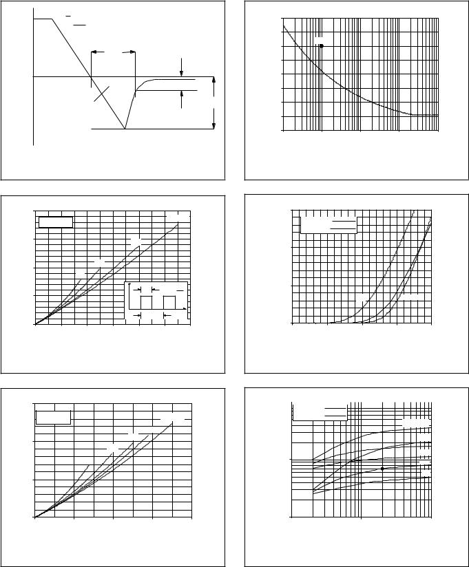
Fig.1. Definition of trr, Qs and Irrm |
|
|
PF / W |
|
BY329 |
|
|
Ths(max) / C |
|||
20 |
|
|
|
|
|
|
|
54 |
|
Vo = 1.25 V |
|
|
|
|
|
D = 1.0 |
|
|
Rs = 0.03 Ohms |
|
|
|
|
|
|
|
15 |
|
|
|
0.5 |
|
|
|
78 |
|
|
|
|
|
|
|
|
|
10 |
|
|
0.2 |
|
|
|
|
102 |
|
0.1 |
|
|
|
|
|
||
|
|
|
|
|
|
|
|
|
|
|
|
I |
|
tp |
|
tp |
|
5 |
|
|
|
|
D = T |
126 |
||
|
|
|
|
|
|
|||
|
|
|
|
|
|
T |
t |
|
|
|
|
|
|
|
|
150 |
|
0 |
|
|
|
|
|
|
|
|
0 |
2 |
4 |
6 |
8 |
|
|
10 |
12 |
|
|
|
IF(AV) / A |
|
|
|
|
|
Fig.2. Maximum forward dissipation, PF = f(IF(AV)); square wave current waveform; parameter D = duty cycle = tp/T.
IFS(RMS) / A |
|
|
BY229 |
|
80 |
|
|
|
|
70 |
|
|
|
|
60 |
IFSM |
|
|
|
|
|
|
|
|
50 |
|
|
|
|
40 |
|
|
|
|
30 |
|
|
|
|
20 |
|
|
|
|
10 |
|
|
|
|
0 |
|
|
|
|
1ms |
10ms |
0.1s |
1s |
10s |
tp / s
Fig.4. Maximum non-repetitive rms forward current. IF = f(tp); sinusoidal current waveform; Tj = 150˚C prior to surge with reapplied VRWM.
IF / A |
|
|
BY229F |
|
30 |
|
|
|
|
|
Tj = 150 C |
|
|
|
|
Tj = 25 C |
|
|
|
20 |
|
|
|
|
10 |
|
|
|
|
|
|
typ |
|
max |
0 |
0.5 |
|
1.5 |
|
0 |
1 |
2 |
||
|
|
VF / V |
|
|
Fig.5. Typical and maximum forward characteristic; IF = f(VF); parameter Tj
PF / W |
|
BY329 |
|
Ths(max) / C |
15 |
|
|
|
78 |
Vo = 1.25 V |
|
|
|
a = 1.57 |
Rs = 0.03 Ohms |
|
|
|
|
|
|
|
|
|
|
|
|
1.9 |
|
10 |
|
|
2.2 |
102 |
|
2.8 |
|
||
|
|
|
|
|
|
|
4 |
|
|
5 |
|
|
|
126 |
0 |
|
|
|
150 |
0 |
2 |
4 |
6 |
8 |
|
|
IF(AV) / A |
|
|
Fig.3. Maximum forward dissipation, PF = f(IF(AV)); sinusoidal current waveform; parameter a = form
factor = IF(RMS)/IF(AV).
10 |
|
Qs / uC |
|
|
|
|
|
|
|
BY329 |
|||
|
Tj = 150 C |
|
|
Tj = 25 C |
IF = 10 A |
|
|
|
|
|
10 A |
|
2 A |
1 A |
|
|
|
1 |
|
2 A |
|
|
|
|
|
1 A |
0.1 |
10 |
|
1 |
100 |
|
|
-dIF/dt (A/us) |
|
Fig.6. Maximum Qs at Tj = 25˚C and 150˚C
October 1994 |
3 |
Rev 1.100 |
Philips Semiconductors |
Product specification |
|
|
Rectifier diodes |
BY229F series |
fast, soft-recovery |
|
|
|
trr / ns |
BY329 |
1000 |
|
|
IF = 10 A |
|
10A |
|
1 A |
|
1A |
100 |
|
Tj = 150 C |
|
Tj = 25 C |
|
10 |
1 |
|
10 |
100 |
|
|
|||
|
|
|
-dIF/dt (A/us) |
|
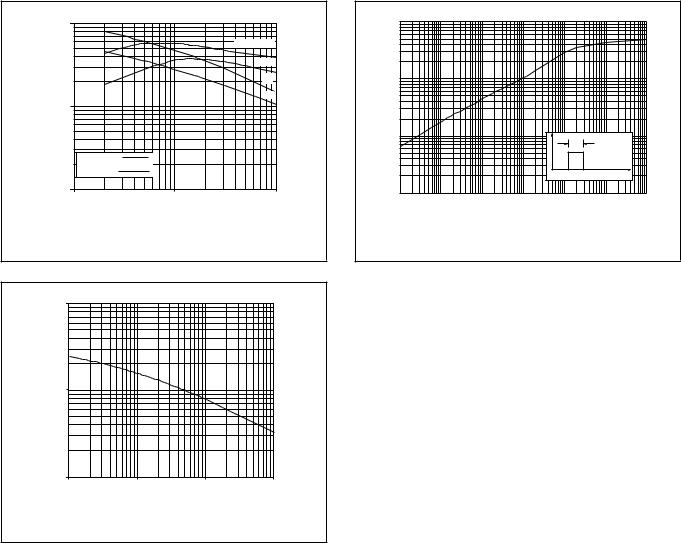
Fig.7. Maximum trr measured to 25% of Irrm; Tj = 25˚C |
||||
|
|
and 150˚C |
|
|
100 |
Cd / pF |
|
|
BY329 |
|
|
|
|
|
10 |
|
|
|
|
1 |
1 |
10 |
VR / V 100 |
1000 |
|
||||
Fig.8. Typical junction capacitance Cd at f = 1 MHz; |
||||
|
|
Tj = 25˚C |
|
|
10 |
Zth j-hs / (K/W) |
|
|
|
|
|
|
1 |
|
|
|
|
|
|
|
0.1 |
|
|
|
PD |
tp |
|
|
|
|
|
|
|
|
||
|
|
|
|
|
|
|
t |
0.01 |
|
|
|
|
|
|
|
10us |
100us |
1ms |
10ms |
0.1s |
1s |
10s |
|
|
|
|
|
tp / s |
|
|
|
Fig.9. Transient thermal impedance Zth = f(tp)
October 1994 |
4 |
Rev 1.100 |
Philips Semiconductors Product specification
Rectifier diodes |
BY229F series |
fast, soft-recovery |
|
|
|
MECHANICAL DATA |
|
Dimensions in mm
|
10.2 |
|
Net Mass: 2 g |
max |
|
|
5.7 |
|
|
max |
0.9 |
|
3.2 |
0.5 |
|
3.0 |
|
4.4
4.0
seating plane
3.5 max |
4.4 |
||
not tinned |
|||
|
|
||
13.5 min
k a
0.4M 


 0.9
0.9
0.7
5.08
4.4 max
2.9 max
7.9
7.5
17 max
0.55 max
1.3
top view
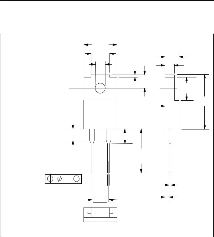
Fig.10. SOD100; The seating plane is electrically isolated from all terminals.
Notes
1.Accessories supplied on request: refer to mounting instructions for F-pack envelopes.
2.Epoxy meets UL94 V0 at 1/8".
October 1994 |
5 |
Rev 1.100 |