Материал: 9871

DISCRETE SEMICONDUCTORS
k, halfpage
M3D168
BYG60 series
Fast soft-recovery
controlled avalanche rectifiers
Preliminary specification |
|
1996 Jun 05 |
|||||
File under Discrete Semiconductors, SC01 |
|
|
|
|
|
|
|
|
|
|
|
|
|
|
|
|
|
|
|
|
|
|
|
|
|
|
|
|
|
|
|

Philips Semiconductors |
Preliminary specification |
|
|
|
|
Fast soft-recovery
BYG60 series
controlled avalanche rectifiers
FEATURES
∙Glass passivated
∙High maximum operating temperature
∙Low leakage current
∙Excellent stability
∙Guaranteed avalanche energy absorption capability
∙UL 94V-O classified plastic package
∙Shipped in 12 mm embossed tape.
DESCRIPTION |
|
|
|
|
The well-defined void-free case is of a |
|||||||||||||||||
DO-214AC surface mountable |
|
transfer-moulded thermo-setting |
||||||||||||||||||||
|
plastic. |
|||||||||||||||||||||
package with glass passivated chip. |
|
|||||||||||||||||||||
|
|
|
|
|
|
|
|
|
|
|
|
|
|
|||||||||
|
|
|
|
|
|
|
|
|
|
|
|
|
|
|
|
|
|
|
|
|
||
handbook, 4 columns |
cathode |
|
|
|
|
|
|
|
|
|
|
|
|
|
|
|||||||
band |
|
|
|
|
|
|
|
|
|
|
|
|
|
|
||||||||
|
|
|
|
|
|
|
|
|
|
|
|
|
|
|
|
|
|
|
|
|||
k |
|
|
|
|
|
|
a |
|
|
|
|
|
|
|
|
|
|
|
|
|||
|
|
|
|
|
|
|
|
|
|
|
|
|
|
|
|
|
|
|
|
|
|
|
|
|
|
|
|
|
|
|
|
|
|
|
|
|
|
|
|
|
|
|
|
|
|
|
|
|
|
|
|
|
|
|
|
|
|
|
|
|
|
|
|
|
|
|
|
|
|
|
|
|
|
|
|
|
|
|
|
|
|
|
|
|
|
|
|
|
|
|
|
|
|
|
|
|
|
|
|
|
|
|
|
|
|
|
|
|
|
|
|
|
|
|
|
|
|
|
|
|
|
|
|
|
|
|
|
|
|
|
|
|
|
|
|
|
|
Top view |
Side view |
MSA474 |
Fig.1 Simplified outline (DO-214AC; SOD106) and symbol.
LIMITING VALUES
In accordance with the Absolute Maximum Rating System (IEC 134).
SYMBOL |
PARAMETER |
CONDITIONS |
MIN. |
MAX. |
UNIT |
|
|
|
|
|
|
VRRM |
repetitive peak reverse voltage |
|
|
|
|
|
BYG60D |
|
− |
200 |
V |
|
BYG60G |
|
− |
400 |
V |
|
BYG60J |
|
− |
600 |
V |
|
BYG60K |
|
− |
800 |
V |
|
BYG60M |
|
− |
1000 |
V |
|
|
|
|
|
|
VR |
continuous reverse voltage |
|
|
|
|
|
BYG60D |
|
− |
200 |
V |
|
BYG60G |
|
− |
400 |
V |
|
BYG60J |
|
− |
600 |
V |
|
BYG60K |
|
− |
800 |
V |
|
BYG60M |
|
− |
1000 |
V |
|
|
|
|
|
|
IF(AV) |
average forward current |
averaged over any 20 ms period; |
− |
1.90 |
A |
|
|
Ttp = 100 °C; see Fig.2 |
|
|
|
|
|
averaged over any 20 ms period; |
− |
0.90 |
A |
|
|
Al2O3 PCB mounting (see Fig.7); |
|
|
|
|
|
Tamb = 60 °C; see Fig.3 |
|
|
|
|
|
averaged over any 20 ms period; |
− |
0.65 |
A |
|
|
epoxy PCB mounting (see Fig.7); |
|
|
|
|
|
Tamb = 60 °C; see Fig.3 |
|
|
|
IFSM |
non-repetitive peak forward current |
t = 10 ms half sine wave; |
− |
25 |
A |
|
|
Tj = Tj max prior to surge; |
|
|
|
|
|
VR = VRRMmax |
|
|
|
1996 Jun 05 |
2 |

Philips Semiconductors Preliminary specification
Fast soft-recovery |
|
BYG60 series |
|||
controlled avalanche rectifiers |
|
||||
|
|
|
|
||
|
|
|
|
|
|
|
|
|
|
|
|
SYMBOL |
PARAMETER |
CONDITIONS |
MIN. |
MAX. |
UNIT |
|
|
|
|
|
|
ERSM |
non-repetitive peak reverse |
L = 120 mH; Tj = Tj max prior to |
|
|
|
|
avalanche energy |
surge; inductive load switched off |
|
|
|
|
BYG60D to J |
|
- |
10 |
mJ |
|
BYG60K and M |
|
- |
7 |
mJ |
|
|
|
|
|
|
Tstg |
storage temperature |
|
-65 |
+175 |
°C |
Tj |
junction temperature |
see Fig.4 |
-65 |
+175 |
°C |
ELECTRICAL CHARACTERISTICS
Tj = 25 °C unless otherwise specified.
SYMBOL |
PARAMETER |
|
CONDITIONS |
MIN. |
TYP. |
MAX. |
UNIT |
|
|
|
|
|
|
|
|
|
|
VF |
forward voltage |
|
IF = 1 A; Tj = Tj max; see Fig.5 |
- |
- |
0.98 |
V |
|
|
|
|
IF = 1 A; see Fig.5 |
- |
- |
1.20 |
V |
|
V(BR)R |
reverse avalanche |
|
IR = 0.1 mA |
|
|
|
|
|
|
breakdown voltage |
|
|
|
|
|
|
|
|
BYG60D |
|
|
|
300 |
- |
- |
V |
|
BYG60G |
|
|
|
500 |
- |
- |
V |
|
BYG60J |
|
|
|
700 |
- |
- |
V |
|
BYG60K |
|
|
|
900 |
- |
- |
V |
|
BYG60M |
|
|
|
1100 |
- |
- |
V |
IR |
reverse current |
|
VR = VRRMmax; |
- |
- |
5 |
mA |
|
|
|
|
see Fig.6 |
|
|
|
|
|
|
|
|
|
|
|
|
|
|
|
|
|
VR = VRRMmax; Tj = 165 °C; |
- |
- |
100 |
mA |
|
|
|
|
see Fig.6 |
|
|
|
|
|
|
|
|
|
|
|
|
|
|
trr |
reverse recovery time |
|
when switched from IF = 0.5 A to |
|
|
|
|
|
|
BYG60D to J |
|
IR = 1 A; measured at IR = 0.25 A; |
- |
- |
250 |
ns |
|
|
BYG60K and M |
|
see Fig.8 |
- |
- |
300 |
ns |
|
|
|
|
|
|||||
|
|
|
|
|
|
|
|
|
Cd |
diode capacitance |
|
VR = 0 V; f = 1 MHz |
|
|
|
|
|
|
BYG60D to J |
|
|
|
- |
30 |
- |
pF |
|
BYG60K and M |
|
|
|
- |
25 |
- |
pF |
|
|
|
|
|
|
|
|
|
THERMAL CHARACTERISTICS |
|
|
|
|
|
|
|
|
|
|
|
|
|
|
|
||
SYMBOL |
|
PARAMETER |
CONDITIONS |
VALUE |
UNIT |
|||
|
|
|
|
|
|
|
||
Rth j-tp |
thermal resistance from junction to tie-point |
|
|
25 |
K/W |
|||
Rth j-a |
thermal resistance from junction to ambient |
note 1 |
|
100 |
K/W |
|||
|
|
|
|
|
note 2 |
|
150 |
K/W |
|
|
|
|
|
|
|
|
|
Notes
1.Device mounted on Al2O3 printed-circuit board, 0.7 mm thick; thickness of copper ³35 mm, see Fig.7.
2.Device mounted on epoxy-glass printed-circuit board, 1.5 mm thick; thickness of copper ³40 mm, see Fig.7. For more information please refer to the ‘General Part of Handbook SC01’.
1996 Jun 05 |
3 |
Philips Semiconductors |
Preliminary specification |
|
|
Fast soft-recovery
BYG60 series
controlled avalanche rectifiers
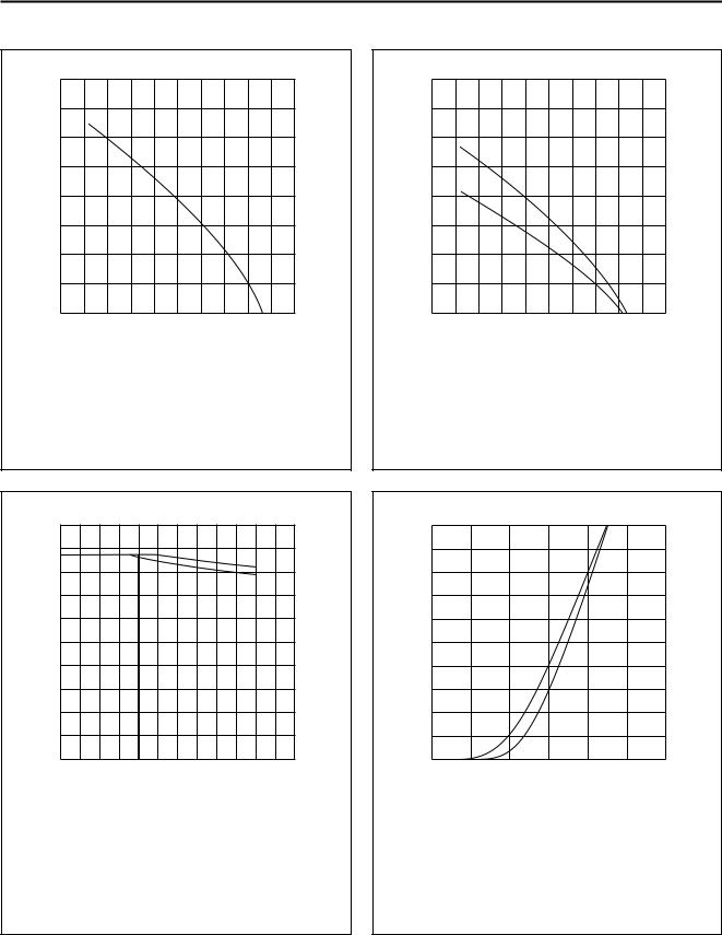
GRAPHICAL DATA
MGD481
4 handbook, halfpage
IF(AV)
(A)
3
2
1
0
0 |
100 |
200 |
|
|
Ttp (°C) |
VR = VRRMmax; δ = 0.5; a = 1.57.
Fig.2 Maximum permissible average forward current as a function of tie-point temperature (including losses due to reverse leakage).
MGD482
1.6 handbook, halfpage
IF(AV)
(A)
1.2
0.8
0.4
0
0 |
100 |
200 |
|
|
Tamb (°C) |
VR = VRRMmax; δ = 0.5; a = 1.57 Device mounted as shown in Fig.7;
solid line: Al2O3 PCB; dotted line: epoxy PCB.
Fig.3 Maximum permissible average forward current as a function of ambient temperature (including losses due to reverse leakage).
MGD483
200 handbook, halfpage
Tj (°C)
160
120
80
D |
G |
J |
K |
M |
40
0
0 |
400 |
800 |
1200 |
|
|
|
VR (V) |
Device mounted as shown in Fig.7
Solid line: Al2O3 PCB
Dotted line: epoxy PCB.
Fig.4 Maximum permissible junction temperature as a function of reverse voltage.
MGD484
10 handbook, halfpage
IF
(A)
8
6
4
2
0
0 |
1 |
2 |
3 |
|
|
|
VF (V) |
Solid line: Tj = 25 °C.
Dotted line: Tj = 175 °C.
Fig.5 Forward current as a function of forward voltage; maximum values.
1996 Jun 05 |
4 |
Philips Semiconductors |
Preliminary specification |
|
|
Fast soft-recovery
BYG60 series
controlled avalanche rectifiers
|
3 |
|
MGC532 |
|
10 |
|
|
|
|
handbook, halfpage |
|
50 |
|
|
|
|
|
|
|
IR |
|
|
|
|
(μA) |
|
|
|
|
10 |
2 |
|
|
|
|
|
|
4.5 |
|
|
|
|
|
50 |
10 |
|
|
2.5 |
|
1 |
0 |
100 |
1.25 |
MSB213 |
|
200 |
|
||
|
|
|
Tj (oC) |
|
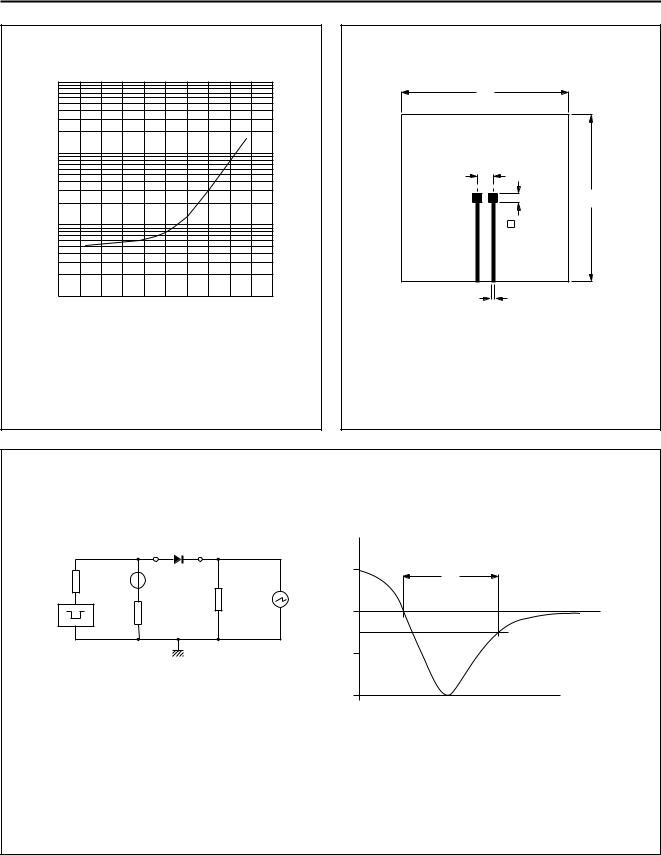
VR = VRMMmax. |
|
Dimensions in mm. |
|
|
|
Material: AL2O3 or epoxy-glass. |
Fig.6 Reverse current as a function of junction |
|
temperature; maximum values. |
Fig.7 Printed-circuit board for surface mounting. |
handbook, full pagewidth |
DUT |
IF |
|
|
|
(A) |
|
|
+ |
0.5 |
t rr |
10 Ω |
25 V |
|
|
|
|
1 Ω |
|
|
50 Ω |
0 |
t |
|
|
|
|
|
|
0.25 |
|
|
|
0.5 |
|
|
|
IR |
|
|
|
(A) |
MAM057 |
|
|
1 |
|
|
|
|
Input impedance oscilloscope: 1 MΩ, 22 pF; tr ≤ 7 ns.
Source impedance: 50 Ω; tr ≤ 15 ns.
Fig.8 Test circuit and reverse recovery time waveform and definition.
1996 Jun 05 |
5 |
Смотрите также:
| Деятельность ООО 'Континент Строй' |