Материал: Calculation of power electronics converters
CONCLUSION
The results of the given course design became constructed and calculated at a three - phase rectifier working on active-inductive load. A design of a rectifier - unitized. The given device has both virtues and a limitation.
Rectifier is such a device that is intended for transformation of alternative voltage into direct one. The main elements of rectifier are transformer and valves, with aid of which there’s provided one-sided current flowing in load circuit, consequently alternative voltage is transformed into pulse one.
Taking into account the initial data
and calculated value of the given rectifier I chose the three-phase bridge
rectifier (Larionov’s scheme) with star-star winding connection. Generally,
schemes of three-phase current rectifiers are applied mostly for power supply
of middle and great power consumers. They uniformly load a network with
three-phase current and are differed due to high coefficient of transformer
usage. Such schemes are used for power supply of static load of active and active-inductive
character, static load with opposite EMF and others.should be mentioned that
nowadays when force semi-conductor valves are used mostly, Larionov’s scheme
has got wide application because of its well technico-economic indicies:
effective usage of transformer, low value of inverse voltage on valve,
comparently low coefficient of pulsation, high efficiency and others. In
three-phased current rectifiers for decreasing of rectified current alternative
component there usually link up inductive smoothing filter in a series with
load, inductance of which has definite value (LH).
Mainly in bridge rectifier there’s no forced magnetization of transformer core
because current in secondary winding flows twice a period, in opposite
directions.
LIST OF THE LITERATURE
1. Варламов Р.Г. Компоновка радиоэлектронной аппаратуры. - М.: Советское радио, 1975.-352с.
2. Справочник конструктора РЭА / Под ред. Варламова Р.Г. - М.: Радио и связь, 1985.-354с.
3. Лярский В.Ф., Мурадян О.Б. Электрические соединители: Справочник. - М.: Радио и связь, 1988.-272с.
4. Электрические кабели и провода, шнуры: Справочник / Под ред. Белоруссова И.И. - М.: Энергоатомиздат, 1987.-536с.
5. Сидоров Н.Н. и др. Малогабаритные трансформаторы и дроссели: Справочник. - М.: Радио и связь, 1985.-540с.
6. Исаков Ю.А. и др. Основы промышленной электроники. - К.: Техника, 1976.-554с.
7. Усатенко С.Т. и др. Выполнение электрических схем по ЕСКД: Справочник. - М.: издательство стандартов, 1989.-325с.
8. Диоды: Справочник / Под ред. Григорьева О.П. и др. - М.: Радио и связь, 1990.-335с.
9. Полупроводниковые приборы. Диоды выпрямительные, стабилитроны, тиристоры: Справочник / Под ред. Голомедова А.В. - М.: Радио и связь, 1983.-523с.
10.Янковенко В.С. и др. Расчет и конструирование элементов электропривода. - М.: Энергоатомиздат, 1987.-320с.
11.
APPENDIX A
Reference data of diodsto the calculated values of Uinv max =92V and Id=2,31A I have chosen in quality of valves the silicic diods of type KD202Г.
The main parameters of the diod type KD202Г:
- maximum available constant (average) direct current =3,5A;
- maximum available constant inverse voltage =100V;
constant inverse current =0,8 mA;
constant (or average) voltage=0,9 B;
enviroment temperature rate: -60 - +30 o ’s depict the construction of this diod:
APPENDIX B
Reference data of throttle.to the calculated value of minimum available inductance of filter throttle Lth min=0,4*10-3Gn and magnetization current I=3,2A I have chosen the throttle of type D201T.main parameters of this throttle:
typedimension of magnetowire ШЛ 5х5;
mass is
equal to 40g.’s depict the construction of the given throttle:
 B - The throttle of the type D201T
The dimensions of the throttle are the following:=12mm=25mm=14mm=27,5mm=4mm=29mm=M2,5
APPENDIX C
Reference data of transformer.to the given data and calculations I chose the transformer of type ТПП 273-127/220-50. Electrical parameters of the transformer are: = 220V - voltage on the primary winding= 127V - voltage on the secondary winding
I= 12A - output current
P= 960 Wt - power =50 Hz -
frequencydimensions:= 50 mm= 81 mm = 92 mm= 10 mm= 88 mm= M5
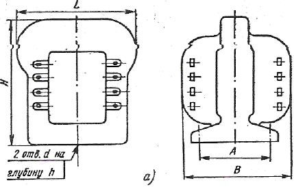
Figure C - Construction of the
transformer of the type ТПП
273-127/220-50
APPENDIX D
Reference data of
clamped connection
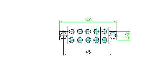 D - Construction of the clamped
connection
D - Construction of the clamped
connection
connection of type Б-324-4 are intended for wire joining and branches in electrotechnical circuits (power, management, signalizings, illuminations and others)of voltage 100 V and frequency 50 Hz.