Материал: MJ10007R
MJ10007
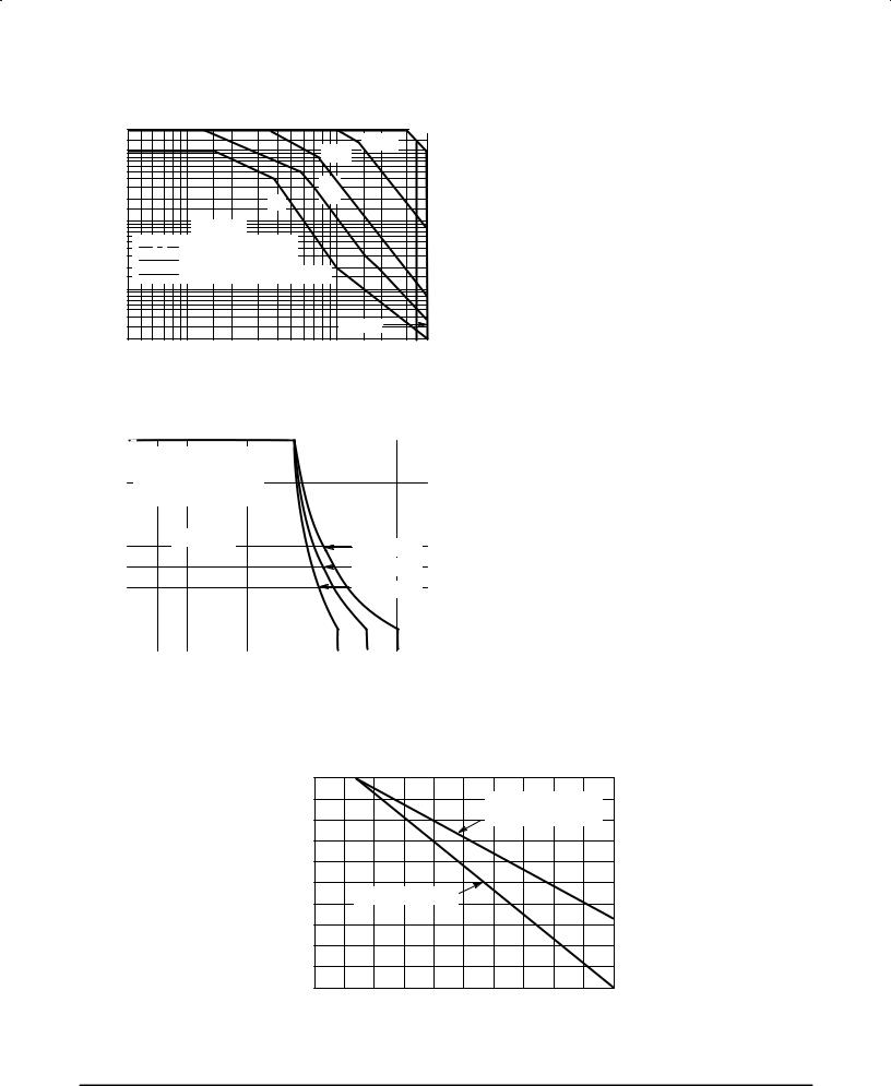
The Safe Operating Area figures shown in Figures 11 and 12 are specified ratings for these devices under the test conditions
shown. |
|
|
|
|
|
|
|
|
|
|
20 |
|
|
|
|
|
|
100 μs |
10 μs |
(AMPS) |
10 |
|
|
|
|
|
1.0 ms |
|
|
|
|
|
|
|
|
|
|||
5.0 |
|
|
|
|
|
|
|
|
|
|
|
|
|
|
|
5.0 |
|
|
|
CURRENT |
|
|
|
|
|
|
|
|
|
2.0 |
|
|
|
dc |
|
ms |
|
|
|
|
|
|
|
|
|
|
|
||
1.0 |
|
T |
= 25°C |
|
|
|
|
|
|
|
|
|
|
|
|
|
|||
COLLECTOR |
0.5 |
|
|
|
|
|
|
||
|
BONDING WIRE LIMITED |
|
|
|
|
||||
|
|
|
|
|
|
||||
0.2 |
|
THERMALLY LIMITED |
|
|
|
|
|||
|
SECOND BREAKDOWN LIMITED |
|
|
||||||
|
|
|
|
||||||
0.1 |
|
|
|
|
|
|
|
|
|
, |
|
|
|
|
|
|
|
|
|
|
|
|
|
|
|
|
|
|
|
C |
|
|
|
|
|
|
|
|
|
I |
0.05 |
|
|
|
|
|
|
|
|
|
|
|
|
|
|
|
|
|
|
|
0.02 |
|
|
|
|
|
MJ10007 |
|
|
|
6.0 |
10 |
20 |
40 |
60 |
|
|
|
|
|
4.0 |
100 |
200 |
350 |
|||||
|
|
|
VCE, COLLECTOR±EMITTER VOLTAGE (VOLTS) |
400 |
|||||
Figure 11. Forward Bias Safe Operating Area
|
10 |
|
|
|
|
|
|
|
|
|
|
|
|
|
|
TURN OFF |
LOAD |
LINE |
|
|
|
|
|
|
|
||
|
|
|
|
|
|
|
|
|
|
||||
(AMP) |
|
|
BOUNDARY |
FOR |
MJ10007 |
|
|
|
|
|
|
||
8 |
|
THE LOCUS |
FOR |
MJ10006 |
|
|
|
|
|
|
|||
|
|
|
|
|
|
|
|
||||||
CURRENT |
|
|
IS 50 V LESS |
|
|
|
|
|
|
|
|
|
|
6 |
|
TJ v 100 |
°C |
|
|
|
|
|
|
|
|
||
COLLECTOR, |
|
|
|
|
|
|
|
|
V |
BE(off) |
= 5 V |
|
|
|
|
|
|
|
|
|
|
|
|
||||
4 |
|
|
|
|
|
|
|
|
V |
BE(off) |
= 2 V |
|
|
|
|
|
|
|
|
|
|
|
|
||||
C |
2 |
|
|
|
|
|
|
|
|
V |
BE(off) |
= 0 V |
|
|
|
|
|
|
|
|
|
|
|
|
|
||
|
|
|
|
|
|
|
|
|
|
|
|
||
I |
|
|
|
|
|
|
|
|
|
|
|
|
|
|
0 |
|
|
|
|
|
|
|
|
|
|
|
|
|
|
|
|
|
|
|
|
|
|
|
|
|
|
|
|
100 |
|
200 |
300 |
400 |
500 |
||||||
|
0 |
|
|||||||||||
VCE, COLLECTOR±EMITTER VOLTAGE (VOLTS)
Figure 12. Reverse Bias Switching
Safe Operating Area
SAFE OPERATING AREA INFORMATION
FORWARD BIAS
There are two limitations on the power handling ability of a transistor: average junction temperature and second breakdown. Safe operating area curves indicate IC ± VCE limits of the transistor that must be observed for reliable operation, i.e., the transistor must not be subjected to greater dissipation than the curves indicate.
The data of Figure 11 is based on TC = 25_C; TJ(pk) is variable depending on power level. Second breakdown pulse
limits are valid for duty cycles to 10% but must be derated when TC ≥ 25_C. Second breakdown limitations do not derate the same as thermal limitations. Allowable current at the voltages shown on Figure 11 may be found at any case temperature by using the appropriate curve on Figure 13.
TJ(pk) may be calculated from the data in Figure 10. At high case temperatures, thermal limitations will reduce the
power that can be handled to values less than the limitations imposed by second breakdown.
REVERSE BIAS
For inductive loads, high voltage and high current must be sustained simultaneously during turn±off, in most cases, with the base to emitter junction reverse biased. Under these conditions the collector voltage must be held to a safe level at or below a specific value of collector current. This can be accomplished by several means such as active clamping, RC snubbing, load line shaping, etc. The safe level for these
devices is specified as VCEX(sus) at a given collector current and represents a voltage±current condition that can be sus-
tained during reverse biased turn±off. This rating is verified under clamped conditions so that the device is never subjected to an avalanche mode. Figure 12 gives the complete reverse bias safe operating area characteristics.
|
100 |
|
|
|
|
|
(%) |
|
|
|
SECOND BREAKDOWN |
|
|
80 |
|
|
DERATING |
|
|
|
FACTOR |
60 |
|
|
|
|
|
DERATING |
40 |
THERMAL DERATING |
|
|
|
|
|
|
|
|
|
||
|
|
|
|
|
|
|
POWER |
20 |
|
|
|
|
|
|
|
|
|
|
|
|
|
0 |
40 |
80 |
120 |
160 |
200 |
|
0 |
|||||
|
|
|
TC, CASE TEMPERATURE (°C) |
|
|
|
Figure 13. Power Derating
6 |
Motorola Bipolar Power Transistor Device Data |
MJ10007
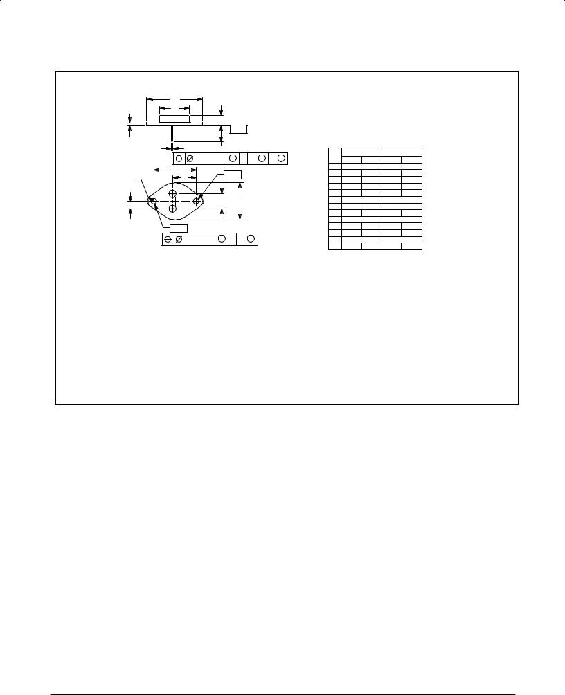
PACKAGE DIMENSIONS
|
A |
|
|
|
|
|
|
|
|
|
|
|
|
N |
|
|
|
|
|
|
NOTES: |
|
|
|
|
|
C |
|
|
|
|
|
|
1. DIMENSIONING AND TOLERANCING PER ANSI |
||||
|
|
|
|
|
|
|
Y14.5M, 1982. |
|
|
|
||
|
|
±T± |
SEATING |
|
|
2. CONTROLLING DIMENSION: INCH. |
|
|||||
|
E |
|
|
PLANE |
|
|
3. ALL RULES AND NOTES ASSOCIATED WITH |
|||||
|
|
|
|
|
|
|
REFERENCED TO±204AA OUTLINE SHALL APPLY. |
|||||
|
D 2 PL |
K |
|
|
|
|
|
|||||
|
|
|
|
|
|
|
INCHES |
MILLIMETERS |
||||
|
|
|
|
|
|
|
|
|||||
|
0.13 (0.005) M |
T |
Q |
M |
Y |
M |
|
|||||
|
DIM |
MIN |
MAX |
MIN |
MAX |
|||||||
|
U |
|
|
|
|
|
|
A |
1.550 REF |
39.37 REF |
||
|
±Y± |
|
|
|
|
B |
±±± |
1.050 |
±±± |
26.67 |
||
V |
L |
|
|
|
|
|||||||
|
|
|
|
|
|
C |
0.250 |
0.335 |
6.35 |
8.51 |
||
|
2 |
|
|
|
|
|
|
D |
0.038 |
0.043 |
0.97 |
1.09 |
|
|
B |
|
|
|
|
E |
0.055 |
0.070 |
1.40 |
1.77 |
|
H |
G |
|
|
|
|
|
G |
0.430 BSC |
10.92 BSC |
|||
1 |
|
|
|
|
|
|
H |
0.215 BSC |
5.46 BSC |
|||
|
|
|
|
|
|
|
K |
0.440 |
0.480 |
11.18 |
12.19 |
|
|
|
|
|
|
|
|
|
|||||
|
|
|
|
|
|
|
|
L |
0.665 BSC |
16.89 BSC |
||
|
±Q± |
|
|
|
|
|
|
N |
±±± |
0.830 |
±±± |
21.08 |
|
0.13 (0.005) M |
T |
Y |
M |
|
|
|
Q |
0.151 |
0.165 |
3.84 |
4.19 |
|
|
|
|
U |
1.187 BSC |
30.15 BSC |
||||||
|
|
|
|
|
|
|
|
V |
0.131 |
0.188 |
3.33 |
4.77 |
|
|
|
|
|
|
|
|
STYLE 1: |
|
|
|
|
|
|
|
|
|
|
|
|
|
PIN 1. BASE |
|
|
|
|
|
|
|
|
|
|
|
|
2. EMITTER |
|
|
|
|
|
|
|
|
|
|
|
CASE: COLLECTOR |
|
|
||
CASE 1±07
TO±204AA (TO±3)
ISSUE Z
Motorola Bipolar Power Transistor Device Data |
7 |

MJ10007
Motorola reserves the right to make changes without further notice to any products herein. Motorola makes no warranty, representation or guarantee regarding the suitability of its products for any particular purpose, nor does Motorola assume any liability arising out of the application or use of any product or circuit, and specifically disclaims any and all liability, including without limitation consequential or incidental damages. ªTypicalº parameters can and do vary in different applications. All operating parameters, including ªTypicalsº must be validated for each customer application by customer's technical experts. Motorola does not convey any license under its patent rights nor the rights of others. Motorola products are not designed, intended, or authorized for use as components in systems intended for surgical implant into the body, or other applications intended to support or sustain life, or for any other application in which the failure of the Motorola product could create a situation where personal injury or death may occur. Should Buyer purchase or use Motorola products for any such unintended or unauthorized application, Buyer shall indemnify and hold Motorola and its officers, employees, subsidiaries, affiliates, and distributors harmless against all claims, costs, damages, and expenses, and reasonable attorney fees arising out of, directly or indirectly, any claim of personal injury or death associated with such unintended or unauthorized use, even if such claim alleges that Motorola was negligent regarding the design or manufacture of the part. Motorola and  are registered trademarks of Motorola, Inc. Motorola, Inc. is an Equal Opportunity/Affirmative Action Employer.
How to reach us: |
|
USA / EUROPE: Motorola Literature Distribution; |
JAPAN: Nippon Motorola Ltd.; Tatsumi±SPD±JLDC, Toshikatsu Otsuki, |
P.O. Box 20912; Phoenix, Arizona 85036. 1±800±441±2447 |
6F Seibu±Butsuryu±Center, 3±14±2 Tatsumi Koto±Ku, Tokyo 135, Japan. 03±3521±8315 |
MFAX: RMFAX0@email.sps.mot.com ± TOUCHTONE (602) 244±6609 HONG KONG: Motorola Semiconductors H.K. Ltd.; 8B Tai Ping Industrial Park, |
|
INTERNET: http://Design±NET.com |
51 Ting Kok Road, Tai Po, N.T., Hong Kong. 852±26629298 |
◊ MJ10007/D
*MJ10007/D*