Материал: Обучение чтению литературы на английском языке по специальности «Радиоэлектронные системы и устройства» (120
electric field is measured in terms of the change of potential over a given distance, e. g. volts per metre, and this is known as the field strength. Similarly when an RF antenna receives a signal the magnetic changes cause a current flow, and the electric field changes cause the voltage changes on the antenna.
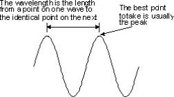
There are a number of properties of a wave. The first is its wavelength (Fig. 1). This is the distance between a point on one wave to the identical point on the next. One of the most obvious points to choose is the peak as this can be easily identified although any point is acceptable.
Fig. 1. Wavelength of an electromagnetic wave
The wavelength of an electromagnetic wave
The second property of the electromagnetic wave is its frequency. This is the number of times a particular point on the wave moves up and down in a given time (normally a second). The unit of frequency is the Hertz and it is equal to one cycle per second. This unit is named after the German scientist who discovered radio waves. The frequencies used in radio are usually very high.
The third major property of the wave is its velocity. Radio waves travel at the same speed as light. For most practical purposes the speed is taken to be 300 000 000 metres per second although a more exact value is 299 792 500 metres per second.
6
Frequency to wavelength conversion
Although wavelength was used as a measure for signals, frequencies are used exclusively today. It is very easy to relate the frequency and wavelength as they are linked by the speed of light as shown:
lambda = c / f
where lambda = the wavelength in metres; f = frequency in Hertz;
c = speed of radio waves (light) taken as 300 000 000 metres per second for all practical purposes.
Field measurements
It is also interesting to note that close to the RF antenna there is also an inductive field the same as that in a transformer. This is not part of the electromagnetic wave, but it can distort measurements close to the antenna. It can also mean that transmitting antennas are more likely to cause interference when they are close to other antennas or wiring that might have the signal induced into it. For receiving antennas they are more susceptible to interference if they are close to house wiring and the like. Fortunately this inductive field falls away fairly rapidly and it is barely detectable at distances beyond about two or three wavelengths from the RF antenna.
(2700)
Answer the following questions.
1. Which way radio signals travel in? 2. What components do electromagnetic waves have? 3. What does electric field result from? 4. What are the main properties of a wave? 5. How is the electric field measured?
Task 1. Find the key-words to speak about electromagnetic waves.
7
Task 2. Find the passage describing the way in which electromagnetic waves affect RF antenna.
Task 3. Write the summary of the text in Russian.
Read text 1B and answer the questions after the text.
Text 1B
Antenna polarisation
Polarisation (or polarization) is an important factor for RF antennas and radio communications in general. Both RF antennas and electromagnetic waves are said to have a polarization.
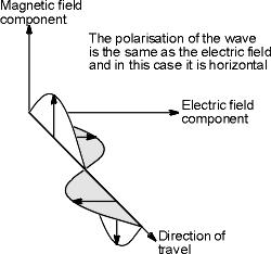
For the electromagnetic wave the polarization is effectively the plane in which the electric wave vibrates. This is important when looking at antennas because they are sensitive to polarisation, and generally only receive or transmit a signal with a particular polarization (Fig. 2).
Fig. 2. An electromagnetic wave
For most antennas it is very easy to determine the polarization. It is simply in the same plane as the elements of the
8
antenna. So a vertical antenna (i.e. one with vertical elements) will receive vertically polarised signals best and similarly a horizontal antenna will receive horizontally polarised signals.
It is important to match the polarization of the RF antenna to that of the incoming signal. In this way the maximum signal is obtained. If the RF antenna polarization does not match that of the signal there is a corresponding decrease in the level of the signal. It is reduced by a factor of cosine of the angle between the polarisation of the RF antenna and the signal.
Accordingly the polarisation of the antennas located in free space is very important, and obviously they should be in exactly the same plane to provide the optimum signal. If they were at right angles to one another (i. e. cross-polarised) then in theory no signal would be received.
For terrestrial radio communications applications it is found that once a signal has been transmitted then its polarisation will remain broadly the same. However reflections from objects in the path can change the polarisation. As the received signal is the sum of the direct signal plus a number of reflected signals the overall polarisation of the signal can change slightly although it remains broadly the same.
Polarisation catagories
Vertical and horizontal are the simplest forms of antenna polarization and they both fall into a category known as linear polarisation. However it is also possible to use circular polarisation. This has a number of benefits for areas such as satellite applications where it helps overcome the effects of propagation anomalies, ground reflections and the effects of the spin that occur on many satellites. Circular polarisation is a little more difficult to visualise than linear polarisation. However it can be imagined by visualising a signal propagating from an RF antenna that is rotating. The tip of the electric field vector will then be seen to trace out a helix or corkscrew as it travels away
9
from the antenna. Circular polarisation can be seen to be either right or left handed dependent upon the direction of rotation as seen from the transmitter.
Another form of polarisation is known as elliptical polarisation. It occurs when there is a mix of linear and circular polarisation. This can be visualised as before by the tip of the electric field vector tracing out an elliptically shaped corkscrew.
However it is possible for linearly polarised antennas to receive circularly polarised signals and vice versa. The strength will be equal whether the linearly polarised antenna is mounted vertically, horizontally or in any other plane but directed towards the arriving signal. There will be some degradation because the signal level will be 3 dB less than if a circularly polarised antenna of the same sense was used. The same situation exists when a circularly polarised antenna receives a linearly polarised signal.
Applications of antenna polarization
Different types of polarisation are used in different applications to enable their advantages to be used. Linear polarization is by far the most widely used for most radio communications applications. Vertical polarisation is often used for mobile radio communications. This is because many vertically polarized antenna designs have an omni-directional radiation pattern and it means that the antennas do not have to be re-orientated as positions as always happens for mobile radio communications as the vehicle moves. For other radio communications applications the polarisation is often determined by the RF antenna considerations. Some large multi-element antenna arrays can be mounted in a horizontal plane more easily than in the vertical plane. This is because the RF antenna elements are at right angles to the vertical tower of pole on which they are mounted and therefore by using an antenna with horizontal elements there is less physical and electrical interference between the two. This determines the standard polarisation in many cases.
10