Материал: 3
Design Considerations,
Testing and Applications 3
Assistance Form
FAST AND LS TTL
FAST AND LS TTL DATA
3-1
DESIGN CONSIDERATIONS
SELECTING TTL LOGIC. TTL Families may be mixed in a system for optimum performance. For instance, in new designs, ALS would commonly be used in non-critical speed paths to minimize power consumption while FAST TTL would be used in high speed paths. The ratio of ALS to FAST will depend on overall system design goals.
NOISE IMMUNITY. When mixing TTL families it is often desirable to know the guaranteed noise immunity for both LOW and HIGH logic levels. Table 3.1 lists the guaranteed logic levels for various TTL families and can be used to calculate noise margin. Table 3.2 specifies these noise margins for systems containing LS, S, ALS and/or FAST TTL. Note that Table 3.2 represents ªworst caseº limits and assumes a maximum power supply and temperature variation across the IC's which are interconnected, as well as maximum rated load. Increased noise immunity can be achieved by designing with decreased maximum allowable operating ranges.
Table 3.1
Worst Case TTL Logic Levels
Electrical Characteristics
|
|
|
Military (± 55 to +125°C) |
Commercial (0 to 70°C) |
|
||||||
|
|
|
|
|
|
|
|
|
|
|
|
|
|
TTL Families |
VIL |
VIH |
VOL |
VOH |
VIL |
VIH |
VOL |
VOH |
Unit |
TTL |
|
Standard TTL 9000, 54/74 |
0.8 |
2.0 |
0.4 |
2.4 |
0.8 |
2.0 |
0.4 |
2.4 |
V |
HTTL |
|
High Speed TTL 54/74H |
0.8 |
2.0 |
0.4 |
2.4 |
0.8 |
2.0 |
0.4 |
2.4 |
V |
LPTTL |
|
Low Power TTL 93L00 (MSI) |
0.7 |
2.0 |
0.3 |
2.4 |
0.8 |
2.0 |
0.3 |
2.4 |
V |
STTL |
|
Schottky TTL 54/74S, 93S00 |
0.8 |
2.0 |
0.5 |
2.5 |
0.8 |
2.0 |
0.5 |
2.7 |
V |
LSTTL |
|
Low Power Schottky TTL 54/74LS |
0.7 |
2.0 |
0.4 |
2.5 |
0.8 |
2.0 |
0.5 |
2.7 |
V |
ALS TTL |
(5% VCC) |
Advanced LS TTL, 54/74ALS |
|
|
|
|
0.8 |
2.0 |
0.5 |
2.75 |
V |
|
(10% VCC) |
|
0.8 |
2.0 |
0.4 |
2.5 |
0.8 |
2.0 |
0.5 |
2.5 |
V |
FAST TTL |
(5% VCC) |
Advanced S TTL, 54/74F |
|
|
|
|
0.8 |
2.0 |
0.5 |
2.7 |
V |
|
(10% VCC) |
|
0.8 |
2.0 |
0.5 |
2.5 |
0.8 |
2.0 |
0.5 |
2.5 |
V |
VOL and VOH are the voltages generated at the output VIL and VIH are the voltage required at the input to generate the appropriate levels. The numbers given above are guaranteed worst-case values.
Table 3.2a
LOW Level Noise Margins (Military)
|
To |
|
|
|
|
|
From |
|
LS |
S |
ALS |
FAST |
Unit |
|
|
|
|
|
|
|
LS |
|
300 |
400 |
400 |
400 |
mV |
S |
|
200 |
300 |
300 |
300 |
mV |
ALS |
|
300 |
400 |
400 |
400 |
mV |
FAST |
|
200 |
300 |
300 |
300 |
mV |
|
|
|
|
|
|
|
From ªV |
º to ªV º |
|
|
|
|
|
OL |
IL |
|
|
|
|
|
Table 3.2c
LOW Level Noise Margins (Commercial)
|
To |
|
|
|
|
|
From |
|
LS |
S |
ALS |
FAST |
Unit |
|
|
|
|
|
|
|
LS |
|
300 |
300 |
300 |
300 |
mV |
S |
|
300 |
300 |
300 |
300 |
mV |
ALS |
|
300 |
300 |
300 |
300 |
mV |
FAST |
|
300 |
300 |
300 |
300 |
mV |
|
|
|
|
|
|
|
From ªV |
º to ªV º |
|
|
|
|
|
OL |
IL |
|
|
|
|
|
Table 3.2b
HIGH Level Noise Margins (Military)
|
To |
|
|
|
|
|
From |
|
LS |
S |
ALS |
FAST |
Unit |
|
|
|
|
|
|
|
LS |
|
500 |
500 |
500 |
500 |
mV |
S |
|
500 |
500 |
500 |
500 |
mV |
ALS |
|
500 |
500 |
500 |
500 |
mV |
FAST |
|
500 |
500 |
500 |
500 |
mV |
|
|
|
|
|
|
|
From ªV |
º to ªV º |
|
|
|
|
|
OH |
IH |
|
|
|
|
|
Table 3.2d
HIGH Level Noise Margins (Commercial)
|
To |
|
|
|
|
|
From |
|
LS |
S |
ALS |
FAST |
Unit |
|
|
|
|
|
|
|
LS |
|
700 |
700 |
700 |
700 |
mV |
S |
|
700 |
700 |
700 |
700 |
mV |
ALS (5% VCC) |
750 |
750 |
750 |
750 |
mV |
|
FAST (5% VCC) |
700 |
700 |
700 |
700 |
mV |
|
ALS (10% VCC) |
500 |
500 |
500 |
500 |
mV |
|
FAST (10% VCC) |
500 |
500 |
500 |
500 |
mV |
|
From ªV |
º to ªV º |
|
|
|
|
|
OH |
IH |
|
|
|
|
|
POWER CONSUMPTION. With the exception of ECL, all logic families exhibit increased power consumption at high frequencies. Care must be taken when switching multiple gates at high frequencies to assure that their combined dissipation does not exceed package and/or device capabilities. TTL devices are more efficient at high frequencies than CMOS.
FAST AND LS TTL DATA
3-2
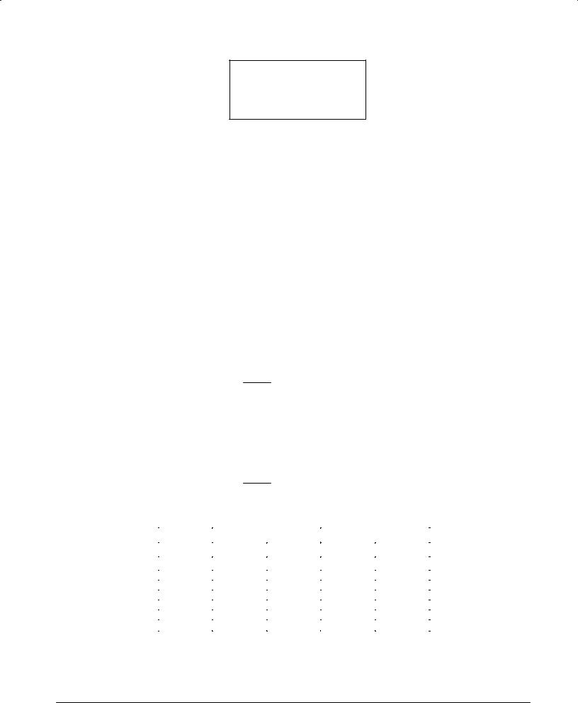
FAN-IN AND FAN-OUT. In order to simplify designing with Motorola TTL devices, the input and output loading parameters of all families are normalized to the following values:
1 TTL Unit Load (U.L.) = 40 μA in the HIGH state (Logic ª1º)
1 TTL Unit Load (U.L.) = 1.6 mA in the LOW state (Logic ª0º)
Input loading and output drive factors of all products described in this handbook are related to these definitions.
EXAMPLES Ð INPUT LOAD
1.A 7400 gate, which has a maximum IIL of 1.6 mA and IIH of 40 μA is specified as having an input load factor of 1 U.L. (Also called a fan-in of 1 load.)
2.The 74LS95B which has a value of IIL = 0.8 mA and IIH of 40 μA on the CP terminal, is specified as having an input LOW load factor of:
0.8 mA |
or 0.5 U.L. and an input HIGH load factor of |
40 μA |
or 1 U.L. |
|
40 μA |
||
1.6 mA |
|
||
3. The 74LS00 gate which has an IIL of 0.4 mA and an IIH of 20 μA, has an input LOW load factor of:
0.4 mA |
or 0.25 U.L. an input HIGH load factor of |
20 μA |
or 0.5 U.L. |
|
40 μA |
||
1.6 mA |
|
||
EXAMPLES Ð OUTPUT DRIVE
1.The output of the 7400 will sink 16 mA in the LOW (logic ª0º) state and source 800μA in the HIGH (logic ª1º) state. The normalized output LOW drive factor is therefore:
16 mA = 10 U.L.
1.6 mA
and the output HIGH drive factor is
800 μA
or 20 U.L.
40μA
2.The output of the 74LS00 will sink 8.0 mA in the LOW state and source 400 μA in the HIGH state. The normalized output LOW drive factor is:
8.0 mA = 5 U.L.
1.6 mA
and the output HIGH drive factor is
400 μA
or 10 U.L.
40 μA
Relative load and drive factors for the basic TTL families are given in Table 3.3.
FAMILY |
INPUT LOAD |
OUTPUT DRIVE |
|||
|
|
|
|
||
HIGH |
LOW |
HIGH |
LOW |
||
|
|||||
|
|
|
|
|
|
74LS00 |
0.5 U.L. |
0.25 U.L. |
10 U.L. |
5 U.L. |
|
7400 |
1 U.L. |
1 U.L. |
20 U.L. |
10 U.L. |
|
9000 |
1 U.L. |
1 U.L. |
20 U.L. |
10 U.L. |
|
74H00 |
1.25 U.L. |
1.25 U.L. |
25 U.L. |
12.5 U.L. |
|
74S00 |
1.25 U.L |
1.25 U.L. |
25 U.L. |
12.5 U.L. |
|
74 ALS |
0.5 U.L |
0.0625 U.L |
10 U.L. |
5 U.L. |
|
74 FAST |
0.5 U.L |
0.375 U.L. |
25 U.L. |
12.5 U.L. |
|
|
|
|
|
|
|
Table 3.3
Values for MSI devices vary significantly from one element to another. Consult the appropriate data sheet for actual characteristics.
FAST AND LS TTL DATA
3-3

WIRED-OR APPLICATIONS. Certain TTL devices are provided with an ªopenº collector output to permit the Wired-OR (actually Wired-AND) function. This is achieved by connecting open collector outputs together and adding an external pull-up resistor.
The value of the pull-up resistor is determined by considering the fan-out of the OR tie and the number of devices in the OR tie. The pull-up resistor value is chosen from a range between maximum value (established to maintain the required VOH with all the OR tied outputs HIGH) and a minimum value (established so that the OR tie fan-out is not exceeded when only one output is LOW).
MINIMUM AND MAXIMUM PULL-UP RESISTOR VALUES
RX(MIN) = |
VCC(MAX) ± VOL |
|
|
RX(MAX) = |
|
|
|
VCC(MIN) ± VOH |
||
I |
± N (LOW) •1.6 mA |
N |
1 |
•I |
OH |
+ N (HIGH) •40 μA |
||||
|
OL |
2 |
|
|
|
|
|
2 |
||
|
|
where: |
|
|
|
|
|
|
|
|
|
|
Rx |
= External Pull-up Resistor |
|
|
|
|
|||
|
|
N1 |
= Number of Wired-OR Outputs |
|
|
|
||||
|
|
N2 |
= Number of Input Unit Loads (U.L.) being Driven |
|||||||
|
|
IOH = ICEX |
= Output HIGH Leakage Current |
|
|
|
||||
|
|
IOL |
= LOW Level Fan-out Current of Driving Element |
|||||||
|
|
VOL |
= Output LOW Voltage Level (0.5 V) |
|
||||||
|
|
VOH |
= Output HIGH Voltage Level (2.4 V) |
|
||||||
|
|
VCC |
= Power Supply Voltage |
|
|
|
|
|||
Example: Four 74LS03 gate outputs driving four other LS gates or MSI inputs.
RX(MIN) = |
|
|
5.25 V ± 0.5 V |
= |
|
4.75 V |
= 742 Ω |
||||
|
|
8.0 mA ± 1.6 mA |
|
|
|||||||
|
|
|
|
|
6.4 mA |
||||||
RX(MAX) = |
|
|
4.75 V ± 2.4 V |
|
|
= |
|
2.35 V |
= 4.9 kΩ |
||
4 |
•100 μA + 2 •40 μA |
||||||||||
|
|
||||||||||
|
|
0.48 mA |
|||||||||
where:
N1
N2 (HIGH) N2 (LOW)
IOH
IOL
VOL
VOH
=4
=4 •0.5 U.L. = 2 U.L.
=4 •0.25 U.L. = 1 U.L.
=100 μA
=8.0 mA
=0.5 V
=2.4 V
Any value of pull-up resistor between 742 Ω and 4.9 kΩ can be used. The lower values yield the fastest speeds while the higher values yield the lowest power dissipation.
UNUSED INPUTS. For best noise immunity and switching speed, unused TTL inputs should not be left floating, but should be held between 2.4 V and the absolute maximum input voltage.
Two possible ways of handling unused inputs are:
1.Connect unused input to VCC, LS and FAST TTL inputs have a breakdown voltage >7.0 V and require, therefore no series resistor.
2.Connect the unused input to the output of an unused gate that is forced HIGH.
CAUTION: Do not connect an unused LS or FAST input to another input of the same NAND or AND function. This method, recommended for normal TTL, increases the input coupling capacitance and thus reduces the ac noise immunity.
INPUT CAPACITANCE. As a rule of thumb, LS and FAST TTL inputs have an average capacitance of 5.0 pF for DIP packages. For an input that serves more than one internal function, each additional function adds approximately 1.5 pF.
FAST AND LS TTL DATA
3-4

LINE DRIVING Ð Because of its superior capacitive drive characteristics, TTL logic is often used in line driving applications which require various termination techniques to maintain signal integrity. Parameters associated with this application are listed in Table 3.4.
It is also often necessary to construct load lines to determine reflection waveforms in line driving applications. The input and output characteristics graphs of section 3 (Figs. 2-4, 2-7 and 2-8) can be very useful for this purpose.
OUTPUT RISE AND FALL TIMES provide important information in determining reflection waveforms and crosstalk coefficients. Typical rise and fall times are approximately 6 ns for LS and about 2.0 ns for FAST with a 50 pF load (measured 10±90%). Output rise and fall times become longer as capacitive load is increased.
INTERCONNECTION DELAYS. For those parts of a system in which timing is critical, designers should take into account the finite delay along the interconnections. These range from about 0.12 to 0.15 ns/inch for the type of interconnections normally used in TTL systems. Exceptions occur in systems using ground planes to reduce ground noise during a logic transition; ground planes give higher distributed capacitance and delays of about 0.15 to 0.22 ns/inch.
Most interconnections on a logic board are short enough that the wiring and load capacitance can be treated as a lumped capacitance for purposes of estimating their effect on the propagation delay of the driving circuit. When an interconnection is long enough that its delay is one-fourth to one-half of the signal transition time, the driver output waveform exhibits noticeable slope changes during a transition. This is evidence that during the initial portion of the output voltage transition the driver sees the characteristic impedance of the interconnection (normally 100 Ω to 200 Ω), which for transient conditions appears as a resistor returned to the quiescent voltage existing just before the beginning of the transition. This characteristic impedance forms a voltage divider with the driver output impedance, tending to produce a signal transition having the same rise or fall time as in the no-load condition but with a reduced amplitude. This attenuated signal travels to the far end of the interconnection, which is essentially an unterminated transmission line, whereupon the signal starts doubling. Simultaneously, a reflection voltage is generated which has the same amplitude and polarity as the original signal, e.g., if the driver output signal is positive-going the reflection will be positive-going, and as it travels back toward the driver it adds to the line voltage. At the instant the reflection arrives at the driver it adds algebraically to the still-rising driver output, accelerating the transition rate and producing the noticeable change in slope.
(ALL MAXIMUM RATINGS) |
|
|
LS |
FAST |
|
||
|
|
|
|
|
|
|
|
Characteristic |
Symbol |
54LSxxx |
|
74LSxxx |
54Fxxx |
74Fxxx |
Unit |
|
|
|
|
|
|
|
|
Operating Voltage Range |
VCC |
5 ± 10% |
|
5 ± 5% |
5 ± 10% |
5 ± 10% |
Vdc |
Output Drive: |
IOH |
±0.4 |
|
±0.4 |
±1.0 |
±1.0 |
mA |
Standard Output |
IOL |
4.0 |
|
8.0 |
20 |
20 |
mA |
|
ISC |
±20 to ±100 |
|
±20 to ±100 |
±60 to ±150 |
±60 to ±150 |
mA |
|
IOH |
±12 |
|
±15 |
±12 |
±15 |
mA |
Buffer Output |
IOL |
12 |
|
24 |
48 |
64 |
mA |
|
ISC |
±40 to ±225 |
|
±40 to ±225 |
±100 to ±225 |
±100 to ±225 |
mA |
Table 3.4
Output Characteristics for Schottky TTL Logic
If an interconnection is of such length that its delay is longer than half the signal transition time, the attenuated output of the driver has time to reach substantial completion before the reflection arrives. In the limit, the waveform observed at the driver output is a 2-step signal with a pedestal. In this circumstance the first load circuit to receive a full signal is the one at the far end, because of the doubling effect, while the last one to receive a full signal is the one nearest the driver since it must wait for the reflection to complete the transition. Thus, in a worst-case situation, the net contribution to the overall delay is twice the delay of the interconnection because the initial part of the signal must travel to the far end of the line and the reflection must return.
When load circuits are distributed along an interconnection, the input capacitance of each will cause a small reflection having a polarity opposite that of the signal transition, and each capacitance also slows the transition rate of the signal as it passes by. The series of small reflections, arriving back at the driver, is subtractive and has the effect of reducing the apparent amplitude of the signal. The successive slowing of the transition rate of the transmitted signal means that it takes longer for the signal to rise or fall to the threshold level of any particular load circuit. A rough but workable approach is to treat the load capacitances as an increase in the intrinsic distributed capacitance of the interconnection. Increasing the distributed capacitance of a transmission line reduces its impedance and increases its delay. A good approximation for ordinary TTL interconnections is that distributed load capacitance decreases the characteristic impedance by about one-third and increases the delay by one-half.
FAST AND LS TTL DATA
3-5