Материал: Scientific Herald of the Voronezh State University of Architecture and Civil Engineering
Issue № 1(29), 2016 ISSN 2075-0811
2.4. Bending resistance of the joints considering the tensile strength [8]:
MN ,Rd M pl,Rd ,b |
1 Nsd / Nb, pl |
, |
(9) |
1 0,5(A 2btf ) / A |
|||
where Mpl, Rd. b is a plastic moment of the support slab of the column: |
|
||
Mpl,Rd,b Wb fyep / Mo ; |
|
(10) |
|
Wb is an inertia moment of the support slab of the column; γМо = 1,1; fyер is the bending resistance of the support slab material; A is the area of the transverse section of the column; Nb, pl is a calculation longitudinal strength of the column base: Nb, pl = Afy / γMo; fy is the compressive resistance of the support slab material; tf is the thickness of the cap of the column section.
2.5. Determining the rigidity of the compressed concrete [7]:
Kc Ec |
leff ,cpbeff ,c |
, |
|
1, 275 |
|||
|
|
where Ec is the elasticity modulus of concrete foundations;
leff ,ср tf 2,5tep.
2.6. Determining the rigidity of a bended support slab [7, 8]: –– without considering extra forces:
|
|
|
|
|
|
l |
|
t3 |
|
|
|
K |
epb |
0,425E |
ep |
eff |
eff |
|
; |
||||
m3 |
|
||||||||||
|
|
|
|
||||||||
–– considering extra forces: |
|
|
|
|
|
|
|
|
|
|
|
|
|
|
|
|
l |
eff |
t3 |
|
|
||
K |
|
0,85E |
|
|
|
eff |
|
, |
|||
|
|
|
m3 |
||||||||
|
|
epb |
ep |
|
|
||||||
where Eep is the elasticity modulus of a steel support slab.
2.7. Determining the rigidity of the tensile bolts [7]: –– without considering extra forces:
Kb Eb 2Ab ;
Lbef
–– without extra forces:
Kb Eb 1,6Ab ,
Lbef
where Ab is the area of the longitudinal section of bolts.
(11)
(12)
(13)
(14)
(15)
101
Scientific Herald of the Voronezh State University of Architecture and Civil Engineering. Construction and Architecture
The equivalence rigidity of the i-th row of bolts [6, 7]:
Kt,i |
|
1 |
|
. |
|
1 |
|
|
1 |
||
|
Kepb,i |
|
Kb,i |
|
|
|
|
|
|
||
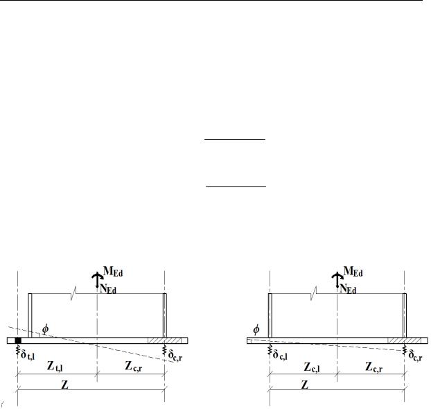
2.8. Determining vertical shears of the connections (Fig. 6.) [6, 9]:
t,l MSd NSd zc,r ;
zKt,l
MSd NSd zt,l .
c,r zKc,r
а) |
b) |
(16)
(17)
(18)
Fig. 6. Mechanical model of the joint:
а) at different signs of efforts in the connections (detachment of the slab from the foundation); b) at identical ones (compressed ones)
2.9. Determining the rotational angle of the support slab (Fig. 6а) [9]:
|
t,l |
|
c,r |
|
1 |
MSd NSd zt,l |
|
MSd NSd zc,r |
|
|
|
|
|
|
|
|
|
. |
|
||||
z |
z |
z2 |
Kc,r |
Kt,l |
|
||||||
|
|
|
|
|
|
(19) |
|||||
|
|
|
|
|
|
|
|
|
|
|
|
2.10. Determining the rotational resistance [5, 9]: –– at a small eccentricity e < zc, r:
S |
r |
|
e |
|
|
|
z2 |
|
|
; |
e e |
|
|
1 |
|
1 |
|
||||
|
|
|
|
(20) |
||||||
|
|
|
0 |
|
|
|
|
|||
|
|
|
|
|
|
Kc,l |
|
|
|
|
|
|
|
|
|
|
|
Kc,r |
|
||
102
Issue № 1(29), 2016 |
ISSN 2075-0811 |
–– at a large eccentricity e > zc, r:
S |
r |
|
e |
|
|
|
z2 |
|
|
, |
e e |
|
|
1 |
|
1 |
|
||||
|
|
|
|
(21) |
||||||
|
|
|
0 |
|
|
|
|
|||
|
|
|
|
|
|
Kt,l |
|
|
|
|
|
|
|
|
|
|
|
Kc,r |
|
||
where Kc, l and Kc, r are the rigidities of the components under tension and shear; μ is the coefficient considering a reduction in the rigidity of a plastic range providing that a bending moment is 2/3 larger than the bending of the components:
1,5 M Sd 2,7 ;
M Rd
e0 Kc zc,r Kt zt,l .
Kc Kt
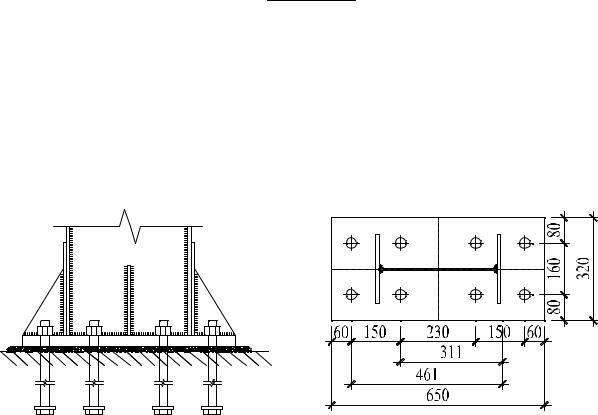
3. Sample calculation. The base of the column is to be computed: the thickness of the support slab is tep = 28 mm, thickness and width of a section of the column tf = 10 mm, bf = 200 mm, twc = 6 mm, hwc = 380 mm; bolts Ab = 560 mm2, fub = 192 N/mm2, FSd = 95 kN; MSd = 170 kN·m; the height of the plate of the concrete foundation h = 1200 mm (Fig. 7).
а) |
b) |
Fig. 7. Distribution of bolts in the column base: а) a cut; b) a plan
The results of the calculation are specified in Table.
103

Scientific Herald of the Voronezh State University of Architecture and Civil Engineering. Construction and Architecture
Table
|
|
|
|
Calculation data |
|
|
|
|
|
|
||||||||||||||
|
|
|
|
|
|
|
|
|
|
|
|
|
|
|
|
|
||||||||
Tensile resistance of the joints of the |
F1,t,Rd |
min Ft,Rd ,1; |
Ft,Rd ,3 min 230750; 193536 |
|||||||||||||||||||||
first row of bolts |
193,5 kN FSd |
95 kN |
|
|
|
|
||||||||||||||||||
|
|
|
|
|
||||||||||||||||||||
Tensile resistance of the joints of the |
F2,t,Rd |
min Ft,Rd ,1; |
Ft,Rd ,3; Fbwt,Rd |
|
||||||||||||||||||||
second row of bolts |
min 319555; 337882; |
|
193536 193,5 |
kN FSd 95 kN |
||||||||||||||||||||
|
|
|||||||||||||||||||||||
Bending resistance of the column base |
M Rd Ft,Rd |
rb Aeff |
f j rc |
|
|
|||||||||||||||||||
|
181,6 kN m MSd |
170 kN m |
|
|
||||||||||||||||||||
Bending resistance of the joint consi- |
M N ,Rd |
M pl,Rd ,b |
|
|
|
|
1 Nsd / Nb, pl |
|
|
|
||||||||||||||
1 0,5(A 2bt f ) / A |
|
|||||||||||||||||||||||
dering the tensile force |
|
|
|
|
|
|
|
|
|
|
|
|
|
|
|
|||||||||
|
173,7 kN m MSd |
|
170 kN m |
|
|
|||||||||||||||||||
|
|
|
MSd NSd zc,r |
|
|
0, 46 mm ; |
|
|
||||||||||||||||
|
|
|
|
|
|
|
|
|
|
|
||||||||||||||
|
t,l |
|
|
|
|
|
|
|
zKt,l |
|
|
|
|
|
|
|
|
|
|
|
|
|||
Displacements of the support slab |
|
|
|
|
|
|
|
|
|
|
|
|
|
|
|
|
|
|
|
|
||||
|
|
|
|
|
MSd NSd zt,l |
|
|
|
|
|
|
|
||||||||||||
|
c,r |
|
|
0,13 mm |
|
|
||||||||||||||||||
|
|
|
|
zKc,r |
|
|
|
|
|
|
|
|||||||||||||
|
|
|
|
|
|
|
|
|
|
|
|
|
|
|
|
|
|
|
|
|
||||
Rotational angle of the support slab |
|
|
t,l |
|
c,r |
|
|
0,46 0,13 1,36 10 3 |
|
|||||||||||||||
|
|
|
|
z |
|
|||||||||||||||||||
|
|
|
|
z |
|
|
|
|
|
|
434,12 |
|
|
|
|
|||||||||
|
Sr |
|
|
e |
|
|
|
|
|
z2 |
|
|
|
10 |
Nmm / radian |
|||||||||
|
|
|
|
|
|
|
|
|
|
|
|
|
|
|
|
|
|
1,95 10 |
||||||
Rotational resistance |
e |
e0 |
|
|
|
1 |
|
|
|
|
1 |
|
|
|||||||||||
|
|
|
|
|
|
|
|
|
|
|
|
|
|
|||||||||||
|
|
|
|
|
|
|
|
|
|
|
|
|
|
|
|
|
|
|
|
|
|
|||
|
|
|
|
|
|
|
|
|
|
|
|
|
|
|
|
|
|
|||||||
|
|
|
|
|
|
|
|
|
|
|
Kt,l |
|
|
|
|
|
|
|
|
|
|
|
||
|
|
|
|
|
|
|
|
|
|
|
|
|
|
|
Kc,r |
|
|
|
|
|||||
Conclusions
1.A method of the evaluation of the rigidity and strength of joints of metal columns with foundations under the effect of a bending moment and axial vertical force considering the rigidity and strength of members of a joint.
2.A degree of accuracy of calculations using the component method in compliance with the Eurocode 3.
3.The previously suggested [6] method of predicting the operation of members of a joint due to more accurate determination of the sizes and shapes of elastic and plastic compressive zones depending on the models suggested in [5, 6, 9].
References
1.Evrokod-2 (TKP EN 1992). Proektirovanie zhelezobetonnyx konstrukcij. — CEN Bryussel', 2004.
2.Evrokod-3 (TKP EN 1993-1-8). Proektirovanie stal'nyx konstrukcij. Ch. 1—8. — CEN Bryussel', 2005.
3.Ledenyov, V. V. Raschet boltovyx soedinenij s uchetom dopolnitel'nyx sil / V. V. Ledenyov, T'yu Txi Xoang An' // Stroitel'naya mexanika i konstrukcii. — 2013. — № 2 (7). — S. 80—85.
4.SNiP 53-100-2010. Stal'nye konstrukcii / Gosstroj Rossii. — M.: GUP CPP, 2010. — 225 s.
104
Issue № 1(29), 2016 |
ISSN 2075-0811 |
5.James, A. S. Ultimate Strength Prying Models for Bolted T-stub Connections / A. S. James // Engineering Journal, American Institute of Steel Construction. — 2002. — № 3. — P. 136—147.
6.Kestutis, U. Component Method Extension to Steel Beam-to-Beam and Beam-to-Column Knee Joints under Bending and Axial Strengths / Kestutis Urbonas, Alfonsas Daniūnas // Journal of Civil Engineering and Management. — 2005. — № 11 (3). — P. 217—224.
7.Latour, M. Column-Base Plate Joints under Monotonic Loads: Theoretical and Experimental Analysis / Massimo Latour, Vincenzo Piluso, Gianvittorio Rizzano // 7th International Workshop on Connections in Steel Structures. — Timisoara, 2012. — 12 pp.
8.Thornton, W. A. Prying Action — a General Treatment / W. A. Thornton // Engineering Journal, American Institute of Steel Construction. — 1985. — Vol. 22, № . 2. — P. 67—75.
9.Wald, F. Component Method for Steel Column Bases / F. Wald, Z. Sokol, C. M. Steenhuis // Heron — Steel Column Bases. — 2008. — Vol. 53, № 1 (2). — 20 pp.
105