Материал: Scientific Herald of the Voronezh State University of Architecture and Civil Engineering
Scientific Herald of t he Voronezh State University o f Architecture and Civil Engineering. Construction and Architecture
а) |
b) |
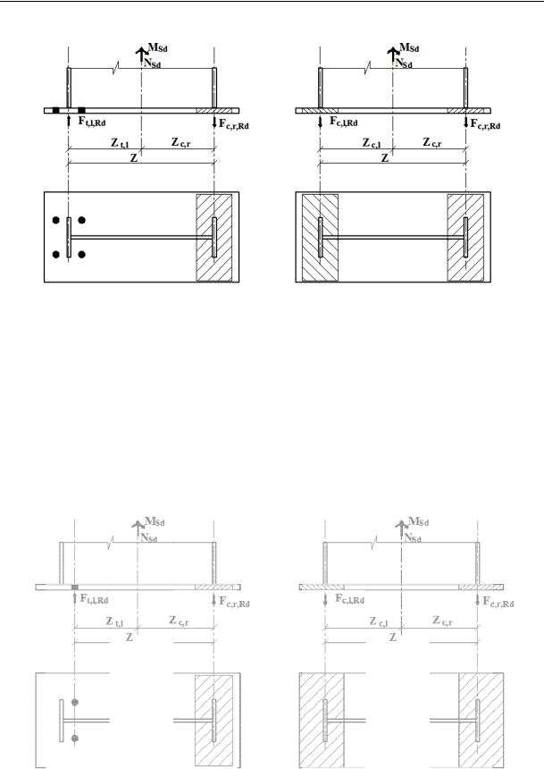
Fig. 2. Strengths applied to a support sla b:
а) two r ows of anchor bolts are stretched, the slab is compressed under the right cap; b) support slab is compressed under both c aps;
Ft, l, Rd is a tensile loa on the left part of the sup port slab;
is a compressive str ength on the right part of the support sla ;
|
Fc, l, Rd is a co mpressive strength on the left part of th |
support slab; |
||||
|
MSd is bending mo ment; NSd is a longitudinal strength; |
|||||
zc, l is an arm of the left compressive strength; zc, r is a n arm of the |
ight compressive strength; |
|||||
|
zt, l is an arm of the right tensile strength; z is |
n arm |
||||
( distance betw een the centres of the stretched and compressed zone s) |
||||||
|
c) |
d) |
||||
|
|
|
|
|
|
|
|
|
|
|
|
|
|
|
|
|
|
|
|
|
|
|
|
|
|
|
|
|
|
|
|
|
|
|
|
|
|
|
|
|
|
|
|
|
|
|
|
|
Fig. 2 (end). Strength applied to the support slab:
c)a r ow of anchor bolts is stretc hed, the slab is compressed under the right cap;
d)the same as “b” but the tension areas of the slab reach the edges
96
Issue № 1(29), 2016 |
ISSN 2075-0811 |
а) |
|
ep |
ep |
x |
|
x |
|
e) |
|
|
ep |
|
ep |
x |
|
|
ep |
b) |
f) |
c) |
g) |
d) |
h) |
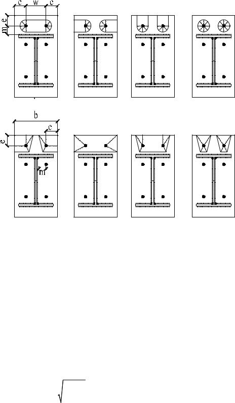
Fig. 3. Scheme of the failure of the support slab:
а, h) plastic areas are joined together; b) plastic areas reaches the transverse and longitudinal sides of the support slab;
c, g) the same for the transverse one; d) round plastic zones; e) angular plastic zones; f) rectangular plastic zones
2. Solution of the problem
2.1. Determining the compressive resistance of the joints as a minimum of the function [5, 7]:
|
|
|
Ft,Rd min FRd ,1, FRd ,2 , FRd ,3 . |
|
(1) |
||||||||
Considering extra forces at |
|
|
|
|
|
|
|
|
|
|
|
|
|
tp 2,07m 3 |
Ab |
|
tep : |
|
|
|
|
|
|
|
|||
|
|
|
|
|
|
|
|
|
|||||
|
|
Lbef leff |
|
|
|
|
|
|
|
|
(2) |
||
|
(8n 2d)M |
|
|
2M |
|
n |
F |
|
|||||
|
|
|
|
||||||||||
|
pl,1,Rd |
|
pl,2,Rd |
|
|
||||||||
Ft,Rd min |
|
|
|
|
; |
|
|
t,Rd |
; |
Ft,Rd ,b |
; |
||
|
|
|
|
|
|
|
|
|
|||||
|
2mn d (m n) |
|
m n |
|
|
||||||||
|
|
|
|
|
|
|
|
|
|
|
|
|
|
97
Scientific Herald of the Voronezh State University of Architecture and Civil Engineering. Construction and Architecture
without considering extra forces at
tp 2,07m3 |
Ab |
tep : |
|
||||
Lbef leff |
(3) |
||||||
|
|
|
|
||||
|
2M |
|
|
|
|||
pl,1,Rd |
|
||||||
Ft,Rd min |
|
|
; Ft,Rd ,b |
, |
|||
|
|
|
|||||
|
m |
|
|
|
|||
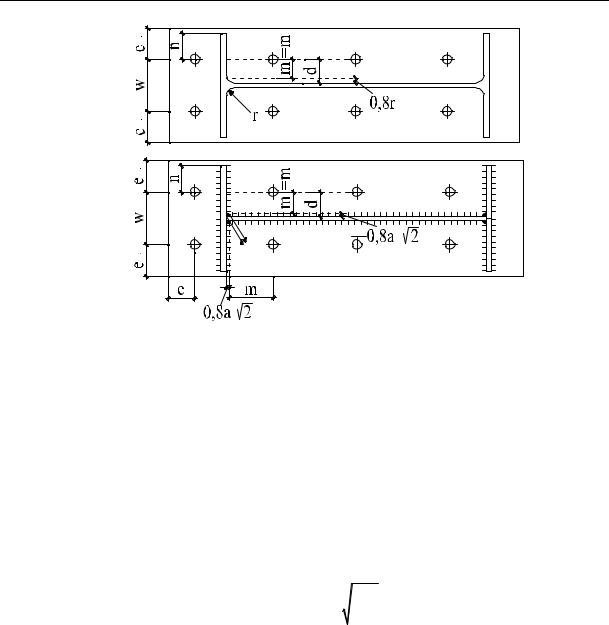
where m is the distance between plastic hinges and the axis of the bolt (for a welded column m ec 0,8ac 2 , ac is the height of the leg of the weld; ec is the distance between the axes of the compressed bolts to the column cap; for a rolled beam m ec 0,8r , n is the distance be-
tween the extra strength Q and axes of the bolts ≤1,25m); d is the diameter of the plate; Lbef is the effective length of anchor bolts:
Lbef 8db tg tep tn / 2,
where db is the diameter of anchor bolts; tg is the thickness of the base between the support slab and the upper one with the foundation base; tn is the thickness of the plate; Mpl,1, Rd, Mpl,2, Rd are plastic bending moments of the support slab corresponding to the first and second failure mechanisms:
|
l |
t2 |
f |
y,ep |
|
M pl,Rd |
eff |
ep |
|
, |
|
|
|
|
|
||
|
|
4 Mo |
|||
where leff is the effective length of the compressed zone of the support slab:
leff min 4m 1, 25ex ; 4 m; 0,5b; 2m 0,625ex 0,5w;2m 0,625ex eep ; 2 m 4eep ; 2 m w ;
tep is the thickness of the support slab; fy, ер is the bending resistance of the support slab material;
γМо is the coefficient: γМо = 1; w is the distance between two axes of bolts; b is the thickness of the support slab; ex, eep are geometrical characteristics (Fig. 3, 4); Ft, Rd, b is a calculated compressive resistance of anchor bolts:
FRd ,3 |
Ft,Rd ,b , Ft,Rd ,b |
0,9As fub |
; |
(4) |
|
||||
|
|
Mb |
|
|
As is the area of the longitudinal section of tensile bolts; fub is the tensile resistance of bolts; γМb = 1,1 is the coefficient.
98
Issue № 1(29), 2016 |
|
|
ISSN 2075-0811 |
а) |
|
ep |
|
ep |
|
|
|
|
|
c |
c |
ep |
|
c |
c |
|
|
||
|
|
|
|
b) |
|
ep |
|
ep |
|
|
|
|
|
c |
c |
|
c |
|
c |
ep |
a |
|
|
|
|
|
|
|
x |
2 |
|
|
c |
|
|
Fig. 4. Denotation of the sizes used in the calculation of the column: а) of a rolled section; b) of a welded section
2.2. Compressive resistance of the joints [1, 7]:
|
|
Mc,Rd |
|
|
|
|
|
|
|
|
|
Fс,Rd |
min f jbeff leff ,c ; |
|
|
, |
(5) |
|
|||||
|
|
hc tcf |
|
|
|
|
|
|
|
|
|
where fj is the compressive resistance of concrete under concentrated axial loads determined according to the European Standard [1]:
f j |
2k j fck |
; k j |
a b |
, |
|
|
1 1 |
||||
3 c |
ab |
||||
|
|
|
where fck is the compressive resistance of concrete; a, b is the width and length of the support slab (Fig. 5);
a1 min a 2ar ; 5a; a h; 5b1
b1 min a 2br ; 5b; b h; 5a1
h is the height of a concrete base plate; γс = 1,5; beff, с, leff, с the compressed zone of T-shaped section:
иa1 a;
иb1 b;
is the effective width and length of
A |
|
Fsd Ft ,Rd ,b |
, b |
|
Aeff ,c |
, l |
b 2c , |
|
|
||||||||
|
||||||||
eff ,c |
|
|
eff ,c |
|
b 2c |
eff ,c |
|
|
|
|
f j |
|
|
|
|||
99
Scientific Herald of the Voronezh State University of Architecture and Civil Engineering. Construction and Architecture
bc, c are the sizes specified according to Fig.5; Mc, Rd is a plastic moment in the column considering the shear and axial strengths (according to the European Standard [2]):
at e = Msd/Nsd > zc, r:
Mc,Rd min Ft,l,Rd z NSd zc,r ; Ft,l,Rd z NSd zt,l ; |
(6) |
at e = Msd/Nsd < zc, r: |
|
Mc,Rd min Fc,l,Rd z NSd zc,r ; Fc,r,Rd z NSd zc,l . |
(7) |
а)
|
1 |
r |
r |
|
r |
|
1 |
b) |
|
|
c |
|
c |
|
|
c |
eff |
|
|
c |
b |
b |
c |
|
|
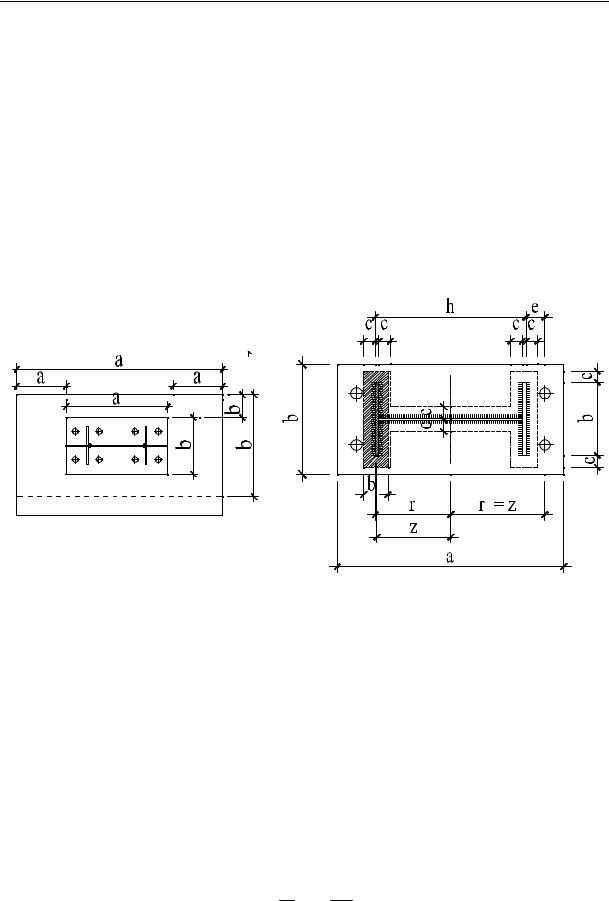
Fig. 5. Sizes of the column base:
а) position of the column on the support slab; b) position of the effective compressed zone on the support slab
2.3. Bending resistance of the column base [1, 7]:
MRd Ft,Rd rb Aeff f j rc , |
(8) |
||
where rb is the distance between the axes of the tensile bolts to the neutral line: |
|
||
r |
hc e ; |
|
|
b |
2 |
c |
|
|
|
|
|
rc is the distance between the centre of the compressed zone to the neutral line:
rc h2c c b2eff .
100