Материал: mur1620ctrev2dx
MOTOROLA
SEMICONDUCTOR TECHNICAL DATA
Order this document by MUR1620CT/D
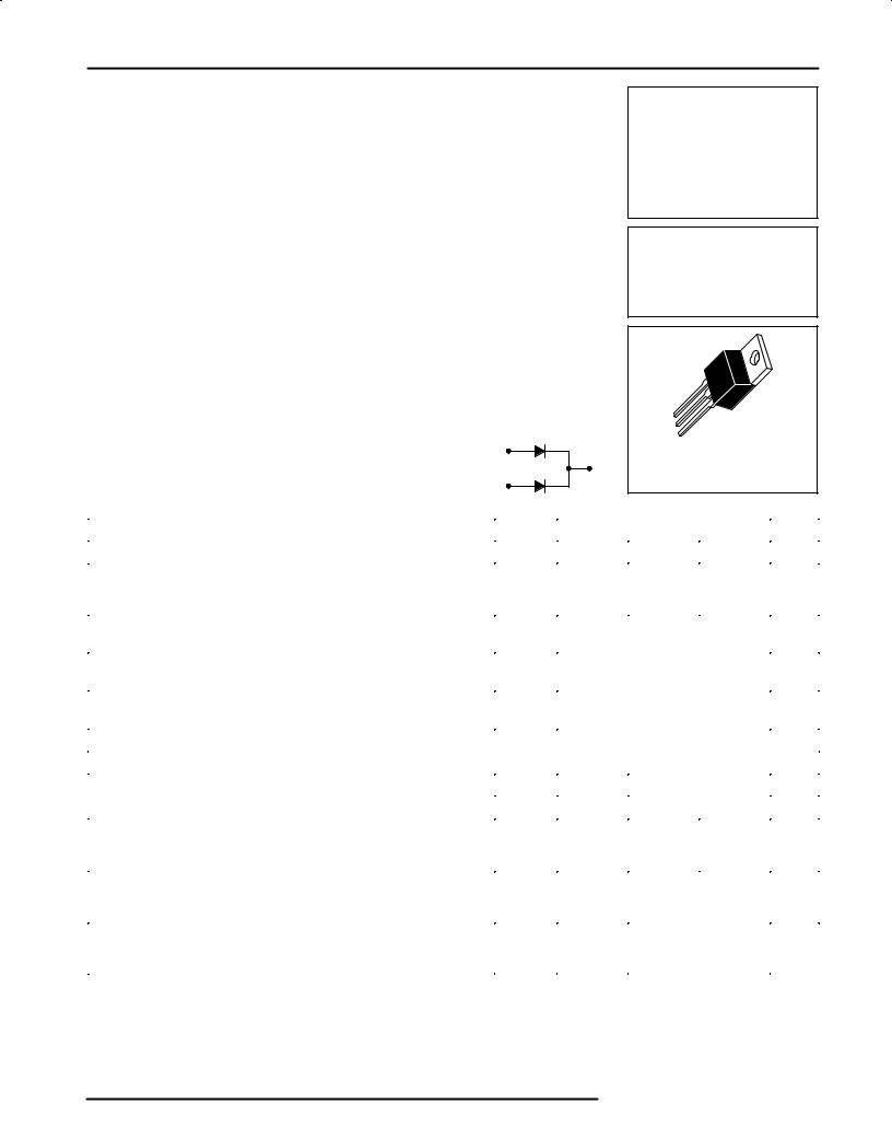
SWITCHMODE Power Rectifiers
. . . designed for use in switching power supplies, inverters and as free wheeling diodes, these state±of±the±art devices have the following features:
•Ultrafast 35 and 60 Nanosecond Recovery Times
•175°C Operating Junction Temperature
•Popular TO±220 Package
•Epoxy Meets UL94, VO @ 1/8″
•High Temperature Glass Passivated Junction
•High Voltage Capability to 600 Volts
•Low Leakage Specified @ 150°C Case Temperature
•Current Derating @ Both Case and Ambient Temperatures
Mechanical Characteristics:
•Case: Epoxy, Molded
•Weight: 1.9 grams (approximately)
•Finish: All External Surfaces Corrosion Resistant and Terminal Leads are Readily Solderable
•Lead Temperature for Soldering Purposes: 260°C Max. for 10 Seconds
•Shipped 50 units per plastic tube
• Marking: U1620, U1640, U1660 |
1 |
|
2, 4 |
|
3 |
MAXIMUM RATINGS |
|
MUR1620CT
MUR1640CT
MUR1660CT
Motorola Preferred Devices
ULTRAFAST
RECTIFIERS
8 AMPERES
200±400±600 VOLTS
4
1
2
3
CASE 221A±06
TO±220AB
|
|
|
|
MUR |
|
|
|
Rating |
|
Symbol |
|
|
|
|
Unit |
|
1620CT |
1640CT |
|
1660CT |
|||
|
|
|
|
|
|
|
|
Peak Repetitive Reverse Voltage |
|
VRRM |
200 |
400 |
|
600 |
Volts |
Working Peak Reverse Voltage |
|
VRWM |
|
|
|
|
|
DC Blocking Voltage |
|
VR |
|
|
|
|
|
Average Rectified Forward Current |
Per Leg |
IF(AV) |
|
8.0 |
|
|
Amps |
Total Device, (Rated VR), TC = 150°C |
Total Device |
|
|
16 |
|
|
|
Peak Rectified Forward Current |
Per Diode Leg |
IFM |
|
16 |
|
|
Amps |
(Rated VR, Square Wave, 20 kHz), TC = 150°C |
|
|
|
|
|
|
|
Nonrepetitive Peak Surge Current |
|
IFSM |
|
100 |
|
|
Amps |
(Surge applied at rated load conditions halfwave, single phase, 60 Hz) |
|
|
|
|
|
|
|
|
|
|
|
|
|
|
|
Operating Junction Temperature and Storage Temperature |
|
TJ, Tstg |
|
65 to +175 |
|
°C |
|
THERMAL CHARACTERISTICS, PER DIODE LEG |
|
|
|
|
|
|
|
|
|
|
|
|
|
|
|
Maximum Thermal Resistance, Junction to Case |
|
RθJC |
3.0 |
2.0 |
|
°C/W |
|
ELECTRICAL CHARACTERISTICS, PER DIODE LEG |
|
|
|
|
|
|
|
|
|
|
|
|
|
|
|
Maximum Instantaneous Forward Voltage (1) |
|
vF |
|
|
|
|
Volts |
(iF = 8.0 Amps, TC = 150°C) |
|
|
0.895 |
1.00 |
|
1.20 |
|
(iF = 8.0 Amps, TC = 25°C) |
|
|
0.975 |
1.30 |
|
1.50 |
|
Maximum Instantaneous Reverse Current (1) |
|
iR |
|
|
|
|
μA |
(Rated dc Voltage, TC = 150°C) |
|
|
250 |
500 |
|
|
|
(Rated dc Voltage, TC = 25°C) |
|
|
5.0 |
10 |
|
|
|
Maximum Reverse Recovery Time |
|
trr |
|
|
|
|
ns |
(IF = 1.0 Amp, di/dt = 50 Amps/μs) |
|
|
35 |
60 |
|
|
|
(IF = 0.5 Amp, IR = 1.0 Amp, IREC = 0.25 Amp) |
|
|
25 |
50 |
|
|
|
(1) Pulse Test: Pulse Width = 300 μs, Duty Cycle ≤ 2.0%
SWITCHMODE is a trademark of Motorola, Inc.
Preferred devices are Motorola recommended choices for future use and best overall value.
Rev 2
Rectifier Device Data
Motorola, Inc. 1996
MUR1620CT MUR1640CT MUR1660CT
|
100 |
|
|
|
70 |
|
|
|
50 |
|
|
|
30 |
|
|
(AMPS) |
20 |
|
|
TJ = 175°C |
100°C |
||
|
|||
CURRENT |
10 |
|
|
7.0 |
25°C |
||
|
|||
|
|
||
FORWARD |
5.0 |
|
|
3.0 |
|
||
INSTANTANEOUS, |
|
||
2.0 |
|
||
|
|
||
|
1.0 |
|
|
F |
0.7 |
|
|
i |
|
||
|
0.5 |
|
0.3
0.2
0.1
0.2 |
0.3 |
0.4 |
0.5 |
0.6 |
0.7 |
0.8 |
0.9 |
1.0 |
1.1 |
1.2 |
vF, INSTANTANEOUS VOLTAGE (VOLTS)
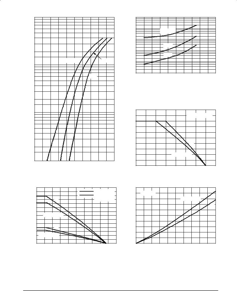
Figure 1. Typical Forward Voltage, Per Leg
(AMPS) |
14 |
|
|
|
|
|
|
|
RqJA = 16°C/W |
|
|
|
|
|
|
|
|
|
|
|
|||
12 |
|
|
|
|
|
|
|
RqJA = 60°C/W |
|
||
CURRENT |
|
|
|
dc |
|
|
|
|
(NO HEATSINK) |
|
|
10 |
|
|
|
|
|
|
|
|
|
|
|
|
|
|
|
|
|
|
|
|
|
|
|
FORWARD |
8.0 |
SQUARE WAVE |
|
|
|
|
|
|
|
||
|
|
|
|
|
|
|
|
||||
6.0 |
|
|
|
|
|
|
|
|
|
|
|
|
|
|
|
|
|
|
|
|
|
|
|
, AVERAGE |
4.0 |
|
|
dc |
|
|
|
|
|
|
|
2.0 |
SQUARE WAVE |
|
|
|
|
|
|
|
|||
F(AV) |
0 |
|
|
|
|
|
|
|
|
|
|
I |
20 |
40 |
60 |
80 |
100 |
120 |
140 |
160 |
180 |
200 |
|
|
0 |
||||||||||
|
|
|
|
TA, AMBIENT TEMPERATURE (°C) |
|
|
|||||
Figure 4. Current Derating, Ambient, Per Leg
|
800 |
|
|
|
|
|
|
|
|
|
|
|
400 |
|
|
|
|
|
|
|
|
|
|
(m A) |
200 |
|
|
|
|
|
|
|
|
|
|
80 |
|
|
|
TJ = 175°C |
|
|
|
|
|
||
CURRENT |
40 |
|
|
|
|
|
|
|
|
||
|
|
|
|
|
|
|
|
|
|
||
|
20 |
|
|
|
|
|
|
|
|
|
|
|
8.0 |
|
|
|
|
|
|
|
|
|
|
REVERSE |
4.0 |
|
|
|
100°C |
|
|
|
|
|
|
0.4 |
|
|
|
|
|
|
|
|
|
||
|
|
|
25°C |
|
|
|
|
|
|
||
|
2.0 |
|
|
|
|
|
|
|
|
|
|
|
0.8 |
|
|
|
|
|
|
|
|
|
|
R |
0.2 |
|
|
|
|
|
|
|
|
|
|
, |
|
|
|
|
|
|
|
|
|
|
|
I |
0.08 |
|
|
|
|
|
|
|
|
|
|
|
|
|
|
|
|
|
|
|
|
|
|
|
0.04 |
|
|
|
|
|
|
|
|
|
|
|
0.02 |
|
|
|
|
|
|
|
|
|
|
|
0 |
20 |
40 |
60 |
80 |
100 |
120 |
140 |
160 |
180 |
200 |
VR, REVERSE VOLTAGE (VOLTS)
Figure 2. Typical Reverse Current, Per Leg*
* The curves shown are typical for the highest voltage device in the voltage grouping. Typical reverse current for lower voltage selections can be estimated from these same curves if VR is sufficiently below rated VR.
(WATTS) |
10 |
|
|
|
|
|
|
|
|
9.0 |
|
|
|
|
RATED VR APPLIED |
|
|||
DISSIPATION |
8.0 |
|
|
|
|
|
|
|
|
7.0 |
|
|
|
|
|
|
|
|
|
6.0 |
|
|
|
|
|
|
|
|
|
|
|
|
|
|
|
|
|
|
|
POWER |
5.0 |
|
|
|
|
|
|
|
|
4.0 |
|
|
|
|
dc |
|
|
|
|
,AVERAGE |
3.0 |
|
|
|
|
|
|
|
|
2.0 |
|
|
|
SQUARE WAVE |
|
|
|
||
1.0 |
|
|
|
|
|
|
|
|
|
F(AV) |
|
|
|
|
|
|
|
|
|
0 |
|
|
|
|
|
|
|
|
|
I |
140 |
145 |
150 |
155 |
160 |
165 |
170 |
175 |
180 |
|
|||||||||
|
|
|
TC, CASE TEMPERATURE (°C) |
|
|
||||
Figure 3. Current Derating, Case, Per Leg
(WATTS) |
10 |
|
|
|
|
|
|
|
|
|
|
9.0 |
TJ = 175°C |
|
|
|
|
|
|
|
|
||
DISSIPATION |
8.0 |
|
|
|
|
|
SQUARE WAVE |
|
|
||
7.0 |
|
|
|
|
|
|
|
|
|
dc |
|
|
|
|
|
|
|
|
|
|
|
||
6.0 |
|
|
|
|
|
|
|
|
|
|
|
|
|
|
|
|
|
|
|
|
|
|
|
POWER |
5.0 |
|
|
|
|
|
|
|
|
|
|
4.0 |
|
|
|
|
|
|
|
|
|
|
|
|
|
|
|
|
|
|
|
|
|
|
|
,AVERAGE |
3.0 |
|
|
|
|
|
|
|
|
|
|
2.0 |
|
|
|
|
|
|
|
|
|
|
|
1.0 |
|
|
|
|
|
|
|
|
|
|
|
F(AV) |
|
|
|
|
|
|
|
|
|
|
|
0 |
|
|
|
|
|
|
|
|
|
|
|
P |
0 |
1.0 |
2.0 |
3.0 |
4.0 |
5.0 |
6.0 |
7.0 |
8.0 |
9.0 |
10 |
|
|||||||||||
IF(AV), AVERAGE FORWARD CURRENT (AMPS)
Figure 5. Power Dissipation, Per Leg
2 |
Rectifier Device Data |
MUR1620CT MUR1640CT MUR1660CT
|
100 |
|
|
|
|
|
|
|
800 |
|
|
|
|
|
|
|
|
|
|
|
|
|
|
|
|
|
|
|
400 |
|
70 |
|
|
|
|
|
|
(m A) |
200 |
|
|
|
|
|
|
|
|
80 |
|
|
50 |
|
|
|
|
|
|
CURRENT |
40 |
|
|
|
|
|
|
|
|
20 |
|
|
30 |
|
|
|
|
|
|
8.0 |
|
|
|
|
|
|
|
|
4.0 |
||
|
|
|
|
|
|
|
REVERSE |
||
|
|
|
|
TJ = 175°C |
|
|
100°C |
2.0 |
|
(AMPS) |
20 |
|
|
|
|
0.8 |
|||
|
|
|
|
|
|
||||
|
|
|
|
|
|
25°C |
0.4 |
||
|
|
|
|
|
|
, |
0.2 |
||
|
|
|
|
|
|
|
R |
||
|
|
|
|
|
|
|
I |
|
|
CURRENT |
10 |
|
|
|
|
|
|
|
0.08 |
|
|
|
|
|
|
|
0.04 |
||
|
|
|
|
|
|
|
|
||
7.0 |
|
|
|
|
|
|
|
0.02 |
|
|
|
|
|
|
|
|
|
||
FORWARD |
5.0 |
|
|
|
|
|
|
|
|
|
|
|
|
|
|
|
|
|
|
,INSTANTANEOUS |
3.0 |
|
|
|
|
|
|
|
|
2.0 |
|
|
|
|
|
|
|
|
|
|
|
|
|
|
|
|
(WATTS) |
10 |
|
F |
1.0 |
|
|
|
|
|
|
||
|
|
|
|
|
|
|
|||
i |
|
|
|
|
|
|
9.0 |
||
|
|
|
|
|
|
|
|||
0.7 |
|
|
|
|
|
|
|
||
|
|
|
|
|
|
|
DISSIPATION |
8.0 |
|
|
0.5 |
|
|
|
|
|
|
7.0 |
|
|
|
|
|
|
|
|
|
||
|
|
|
|
|
|
|
|
6.0 |
|
|
|
|
|
|
|
|
|
|
|
|
0.3 |
|
|
|
|
|
|
POWER |
5.0 |
|
|
|
|
|
|
|
|
||
|
|
|
|
|
|
|
|
4.0 |
|
|
0.2 |
|
|
|
|
|
|
,AVERAGE |
3.0 |
|
|
|
|
|
|
|
|
||
|
|
|
|
|
|
|
|
2.0 |
|
|
0.1 |
|
|
|
|
|
|
1.0 |
|
|
|
|
|
|
|
|
F(AV) |
||
|
0.4 |
0.6 |
0.8 |
1.0 |
1.2 |
1.4 |
1.6 |
0 |
|
|
|
vF, INSTANTANEOUS VOLTAGE (VOLTS) |
|
I |
|
||||
|
|
|
|
|
|||||
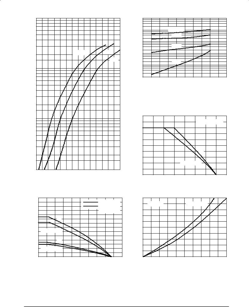
Figure 6. Typical Forward Voltage, Per Leg
TJ = 175°C
150°C
100°C
25°C
0 |
50 |
100 |
150 |
200 |
250 |
300 |
350 |
400 |
450 |
500 |
VR, REVERSE VOLTAGE (VOLTS)
Figure 7. Typical Reverse Current, Per Leg*
* The curves shown are typical for the highest voltage device in the voltage grouping. Typical reverse current for lower voltage selections can be estimated from these curves if VR is sufficiently below rated
VR.
|
|
|
|
|
RATED VR APPLIED |
|
||
|
|
|
|
|
dc |
|
|
|
|
|
|
|
SQUARE WAVE |
|
|
|
|
140 |
145 |
150 |
155 |
160 |
165 |
170 |
175 |
180 |
|
|
TC, CASE TEMPERATURE (°C) |
|
|
||||
(AMPS) |
14 |
|
|
|
|
|
|
|
|
|
|
|
|
|
|
|
|
|
|
RqJA = 16°C/W |
|
||
12 |
|
|
|
|
|
|
|
RqJA = 60°C/W |
|
||
CURRENT |
|
|
|
|
|
|
|
|
|||
|
|
|
|
|
|
|
|
(NO HEAT SINK) |
|||
10 |
|
dc |
|
|
|
|
|
|
|
|
|
|
|
|
|
|
|
|
|
|
|
||
|
|
|
|
|
|
|
|
|
|
|
|
FORWARD |
8.0 |
|
|
|
|
|
|
|
|
|
|
6.0 |
SQUARE WAVE |
|
|
|
|
|
|
|
|
||
|
|
|
|
|
|
|
|
|
|
||
|
|
|
|
|
|
|
|
|
|
|
|
, AVERAGE |
4.0 |
|
dc |
|
|
|
|
|
|
|
|
2.0 |
SQUARE WAVE |
|
|
|
|
|
|
|
|
||
F(AV) |
0 |
|
|
|
|
|
|
|
|
|
|
I |
20 |
40 |
60 |
80 |
100 |
120 |
140 |
160 |
180 |
200 |
|
|
0 |
||||||||||
|
|
|
TA, AMBIENT TEMPERATURE (°C) |
|
|
||||||
Figure 8. Current Derating, Case, Per Leg
(WATTS) |
10 |
|
|
|
|
|
|
|
|
|
|
9.0 |
TJ = 175°C |
|
|
|
SQUARE WAVE |
|
|
dc |
|||
DISSIPATION |
8.0 |
|
|
|
|
|
|
|
|
|
|
7.0 |
|
|
|
|
|
|
|
|
|
|
|
6.0 |
|
|
|
|
|
|
|
|
|
|
|
|
|
|
|
|
|
|
|
|
|
|
|
POWER |
5.0 |
|
|
|
|
|
|
|
|
|
|
4.0 |
|
|
|
|
|
|
|
|
|
|
|
|
|
|
|
|
|
|
|
|
|
|
|
,AVERAGE |
3.0 |
|
|
|
|
|
|
|
|
|
|
2.0 |
|
|
|
|
|
|
|
|
|
|
|
1.0 |
|
|
|
|
|
|
|
|
|
|
|
F(AV) |
|
|
|
|
|
|
|
|
|
|
|
0 |
|
|
|
|
|
|
|
|
|
|
|
P |
0 |
1.0 |
2.0 |
3.0 |
4.0 |
5.0 |
6.0 |
7.0 |
8.0 |
9.0 |
10 |
|
|||||||||||
IF(AV), AVERAGE FORWARD CURRENT (AMPS)
Figure 9. Current Derating, Ambient, Per Leg |
Figure 10. Power Dissipation, Per Leg |
Rectifier Device Data |
3 |
MUR1620CT |
MUR1640CT |
MUR1660CT |
|
|
|
|||||
|
100 |
|
|
|
|
|
|
|
|
800 |
|
|
|
|
|
|
|
|
|
|
|
|
70 |
|
|
|
|
|
|
|
|
400 |
|
|
|
|
|
|
|
|
(m A) |
200 |
|
|
|
|
|
|
|
|
|
|
80 |
|
|
50 |
|
|
|
|
|
|
|
CURRENT |
40 |
|
|
|
|
|
|
|
|
|
20 |
|
|
30 |
|
|
|
|
|
|
|
8.0 |
|
|
|
|
|
|
|
|
|
4.0 |
||
|
|
|
|
TJ = 150°C |
|
|
REVERSE |
|||
|
|
|
|
|
|
|
2.0 |
|||
(AMPS) |
20 |
|
|
|
|
|
|
|
0.8 |
|
|
|
|
|
|
|
|
|
0.4 |
||
|
|
|
|
|
|
|
|
, |
0.2 |
|
|
|
|
|
|
|
100°C |
|
R |
||
|
|
|
|
|
|
|
I |
|
||
CURRENT |
|
|
|
|
|
|
|
|
0.08 |
|
10 |
|
|
|
|
25°C |
|
|
|
||
|
|
|
|
|
|
|
0.04 |
|||
|
|
|
|
|
|
|
|
|||
7.0 |
|
|
|
|
|
|
|
|
0.02 |
|
|
|
|
|
|
|
|
|
|
||
FORWARD |
5.0 |
|
|
|
|
|
|
|
|
|
|
|
|
|
|
|
|
|
|
|
|
,INSTANTANEOUS |
3.0 |
|
|
|
|
|
|
|
|
|
2.0 |
|
|
|
|
|
|
|
|
|
|
|
|
|
|
|
|
|
|
(WATTS) |
10 |
|
F |
1.0 |
|
|
|
|
|
|
|
||
|
|
|
|
|
|
|
|
|||
i |
|
|
|
|
|
|
|
9.0 |
||
|
|
|
|
|
|
|
|
|||
0.7 |
|
|
|
|
|
|
|
|
||
|
|
|
|
|
|
|
|
DISSIPATION |
8.0 |
|
|
0.5 |
|
|
|
|
|
|
|
7.0 |
|
|
|
|
|
|
|
|
|
|
||
|
|
|
|
|
|
|
|
|
6.0 |
|
|
|
|
|
|
|
|
|
|
|
|
|
0.3 |
|
|
|
|
|
|
|
POWER |
5.0 |
|
|
|
|
|
|
|
|
|
||
|
0.2 |
|
|
|
|
|
|
|
4.0 |
|
|
|
|
|
|
|
|
|
,AVERAGE |
3.0 |
|
|
|
|
|
|
|
|
|
|
||
|
|
|
|
|
|
|
|
|
2.0 |
|
|
0.1 |
|
|
|
|
|
|
|
1.0 |
|
|
0.6 |
|
1.0 |
1.2 |
|
|
|
F(AV) |
||
|
0.4 |
0.8 |
1.4 |
1.6 |
1.8 |
0 |
||||
|
|
|
vF, INSTANTANEOUS VOLTAGE (VOLTS) |
|
|
I |
|
|||
|
|
|
|
|
|
|
||||
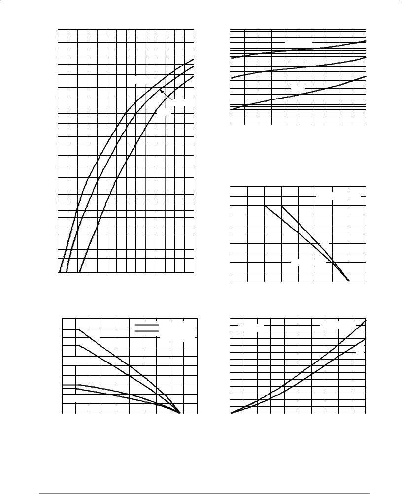
Figure 11. Typical Forward Voltage, Per Leg
|
|
TJ = 150°C |
|
|
|
|
|
|
100°C |
|
|
|
|
|
25°C |
|
|
100 |
200 |
300 |
400 |
500 |
600 |
|
|
VR, REVERSE VOLTAGE (VOLTS) |
|
|
|
Figure 12. Typical Reverse Current, Per Leg*
* The curves shown are typical for the highest voltage device in the voltage grouping. Typical reverse current for lower voltage selections can be estimated from these same curves if VR is sufficiently below rated VR.
|
|
|
|
|
RATED VR APPLIED |
|
||
|
|
|
|
|
dc |
|
|
|
|
|
|
|
SQUARE WAVE |
|
|
|
|
140 |
145 |
150 |
155 |
160 |
165 |
170 |
175 |
180 |
|
|
TC, CASE TEMPERATURE (°C) |
|
|
||||
(AMPS) |
10 |
|
|
|
|
|
|
|
RqJA = 16°C/W |
|
|
9.0 |
|
|
|
|
|
|
|
|
|||
|
|
|
|
|
|
|
RqJA = 60°C/W |
|
|||
|
|
dc |
|
|
|
|
|
|
|||
CURRENT |
8.0 |
|
|
|
|
|
|
(NO HEAT SINK) |
|||
|
|
|
|
|
|
|
|||||
7.0 |
|
|
|
|
|
|
|
|
|
|
|
6.0 |
|
|
|
|
|
|
|
|
|
|
|
FORWARD |
SQUARE WAVE |
|
|
|
|
|
|
|
|
||
5.0 |
|
|
|
|
|
|
|
|
|||
|
|
|
|
|
|
|
|
|
|
||
4.0 |
|
|
|
|
|
|
|
|
|
|
|
AVERAGE |
3.0 |
|
dc |
|
|
|
|
|
|
|
|
|
|
|
|
|
|
|
|
|
|
||
2.0 |
SQUARE WAVE |
|
|
|
|
|
|
|
|
||
|
|
|
|
|
|
|
|
|
|||
, |
1.0 |
|
|
|
|
|
|
|
|
|
|
F(AV) |
|
|
|
|
|
|
|
|
|
|
|
0 |
|
|
|
|
|
|
|
|
|
|
|
I |
20 |
40 |
60 |
80 |
100 |
120 |
140 |
160 |
180 |
200 |
|
|
0 |
||||||||||
|
|
|
TA, AMBIENT TEMPERATURE (°C) |
|
|
||||||
Figure 13. Current Derating, Case, Per Leg
(WATTS) |
14 |
|
|
|
|
|
|
|
|
|
|
13 |
TJ = 175°C |
|
|
|
|
SQUARE WAVE |
|
||||
12 |
|
|
|
|
|
|
|
|
|||
DISSIPATION |
11 |
|
|
|
|
|
|
|
|
|
|
10 |
|
|
|
|
|
|
|
|
|
dc |
|
9.0 |
|
|
|
|
|
|
|
|
|
||
|
|
|
|
|
|
|
|
|
|
||
8.0 |
|
|
|
|
|
|
|
|
|
|
|
POWER |
7.0 |
|
|
|
|
|
|
|
|
|
|
6.0 |
|
|
|
|
|
|
|
|
|
|
|
5.0 |
|
|
|
|
|
|
|
|
|
|
|
,AVERAGE |
|
|
|
|
|
|
|
|
|
|
|
4.0 |
|
|
|
|
|
|
|
|
|
|
|
3.0 |
|
|
|
|
|
|
|
|
|
|
|
2.0 |
|
|
|
|
|
|
|
|
|
|
|
F(AV) |
1.0 |
|
|
|
|
|
|
|
|
|
|
0 |
|
|
|
|
|
|
|
|
|
|
|
P |
0 |
1.0 |
2.0 |
3.0 |
4.0 |
5.0 |
6.0 |
7.0 |
8.0 |
9.0 |
10 |
|
|||||||||||
IF(AV), AVERAGE FORWARD CURRENT (AMPS)
Figure 14. Current Derating, Ambient, Per Leg |
Figure 15. Power Dissipation, Per Leg |
4 |
Rectifier Device Data |
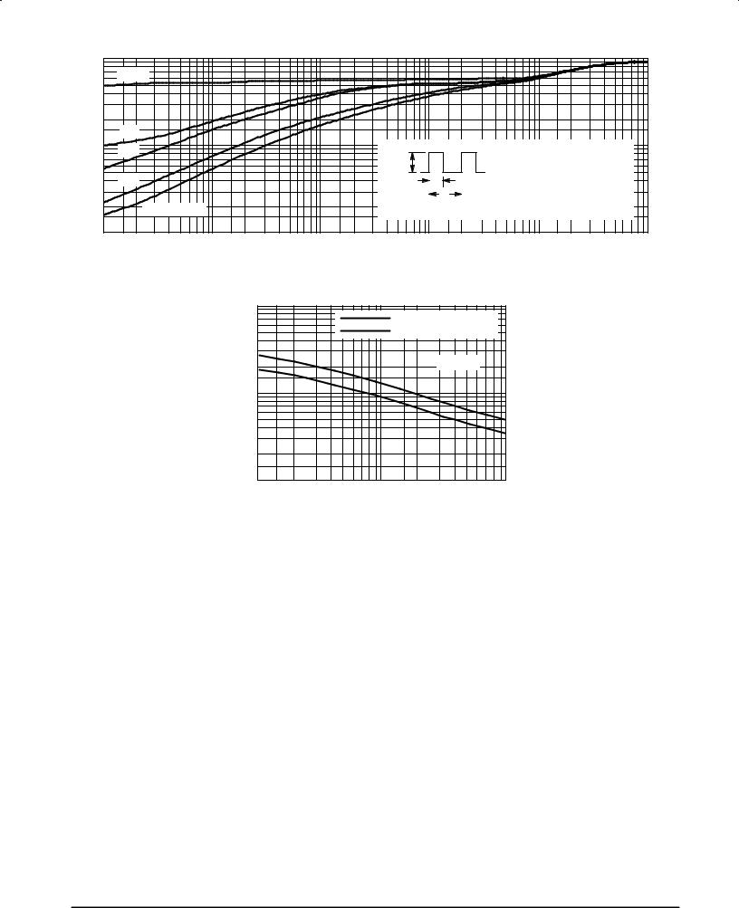
r(t), TRANSIENT THERMAL RESISTANCE (NORMALIZED)
1.0
D = 0.5
0.5
0.2
0.1
0.10.05
0.05
0.01
0.02SINGLE PULSE
0.01
0.01 |
0.02 |
0.05 |
0.1 |
|
|
|
|
|
MUR1620CT |
MUR1640CT |
MUR1660CT |
||||
|
|
|
|
P(pk) |
|
|
ZθJC(t) = r(t) RθJC |
|
|
||
|
|
|
|
|
|
D CURVES APPLY FOR POWER |
|
||||
|
|
|
|
|
t1 |
|
|
||||
|
|
|
|
|
|
PULSE TRAIN SHOWN |
|
|
|||
|
|
|
|
|
|
t2 |
READ TIME AT T1 |
|
|
||
|
|
|
|
DUTY CYCLE, D = t /t |
|
TJ(pk) ± TC = P(pk) ZθJC(t) |
|
||||
|
|
|
|
|
|
1 2 |
|
|
|
|
|
0.2 |
0.5 |
1.0 |
2.0 |
5.0 |
10 |
20 |
50 |
100 |
200 |
500 |
1000 |
|
|
|
t, TIME (ms) |
|
|
|
|
|
|
|
|
Figure 16. Thermal Response
|
1000 |
|
|
|
|
MUR1620CT THRU 1660CT |
|
|
|
MUR1605CT THRU 1615CT |
|
(pF) |
300 |
TJ = 25°C |
|
|
|
||
C, CAPACITANCE |
|
|
|
100 |
|
|
|
30 |
|
|
|
|
|
|
|
|
10 |
|
|
|
1.0 |
10 |
100 |
|
|
VR, REVERSE VOLTAGE (VOLTS) |
|
Figure 17. Typical Capacitance, Per Leg
Rectifier Device Data |
5 |