Материал: [2.1] 3D Imaging, Analysis and Applications-Springer-Verlag London (2012)
84 |
S. Se and N. Pears |
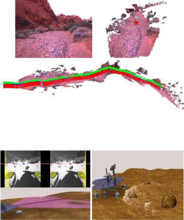
Fig. 2.21 First image of a sequence captured by an autonomous rover in a desert in Nevada (left). Terrain model generated with virtual rover model inserted (right). Resulting terrain model and rover trajectory (bottom). Figure courtesy of [1]
Fig. 2.22 Mars Exploration Rover stereo image processing (left) and the reconstructed color 3D point cloud (right), with a virtual rover model inserted. Figure courtesy of [31]
tary rover exploration due to the limited bandwidth available. Figure 2.21 shows a photo-realistic 3D model created from a moving autonomous vehicle that traveled over 40 m in a desert in Nevada.
One of the key technologies required for planetary rover navigation is the ability to sense the nearby 3D terrain. Stereo cameras are suitable for planetary exploration thanks to their low power and low mass requirements and the lack of moving parts. The NASA Mars Exploration Rovers (MERs), named Opportunity and Spirit, both use passive stereo image processing to measure geometric information about the environment [31]. This is done by matching and triangulating pixels from a pair of rectified stereo images to generate a 3D point cloud. Figure 2.22 shows an example of the stereo images captured and the color 3D point cloud generated which represents the imaged terrain.
2 Passive 3D Imaging |
85 |
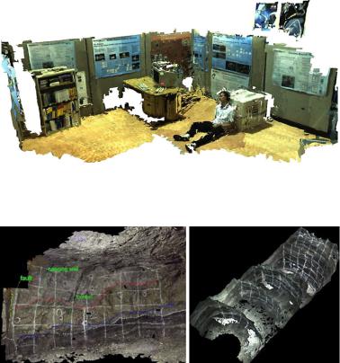
Fig. 2.23 3D model of a mock crime scene obtained with a hand-held stereo camera. Figure courtesy of [48]
Fig. 2.24 Underground mine 3D model (left) and consecutive 3D models as the mine advances (right). The red and blue lines on the left are geological features annotated by geologists to help with the ore body modeling. Figure courtesy of [48]
Documenting crime scenes is a tedious process that requires the investigators to record vast amounts of data by using video, still cameras and measuring devices, and by taking samples and recording observations. With passive 3D imaging systems, 3D models of the crime scene can be created quickly without much disturbance to the crime scene. The police can also perform additional measurements using the 3D model after the crime scene is released. The 3D model can potentially be shown in court so that the judge and the jury can understand the crime scene better. Figure 2.23 shows a 3D reconstruction of a mock crime scene generated from a hand-held stereo sequence within minutes after acquisition [48].
Photo-realistic 3D models are useful for survey and geology in underground mining. The mine map can be updated after each daily drill/blast/ore removal cycle to minimize any deviation from the plan. In addition, the 3D models can also allow the mining companies to monitor how much ore is taken at each blast. Figure 2.24 shows a photo-realistic 3D model of an underground mine face annotated with ge-
86 |
S. Se and N. Pears |
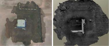
Fig. 2.25 3D reconstruction of a building on the ground using video (left) and using infra-red video (right) captured by an UAV (Unmanned Aerial Vehicle). Figure courtesy of [50]
ological features and consecutive 3D models of a mine tunnel created as the mine advances [48].
Airborne surveillance and reconnaissance are essential for successful military missions. Unmanned Aerial Vehicles (UAVs) are becoming the platform of choice for such surveillance operations and video cameras are among the most common sensors onboard UAVs. Photo-realistic 3D models can be generated from UAV video data to provide situational awareness as it is easier to understand the scene by visualizing it in 3D. The 3D model can be viewed from different perspectives and allow distance measurements and line-of-sight analysis. Figure 2.25 shows a 3D reconstruction of a building on the ground using video and infra-red video captured by an UAV [50]. The photo-realistic 3D models are geo-referenced and can be visualized in 3D Geographical Information System (GIS) viewers such as Google Earth.
2.9.3 Mobile Robot Localization and Mapping
Mobile robot localization and mapping is the process of simultaneously tracking the position of a mobile robot relative to its environment and building a map of the environment. Accurate localization is a prerequisite for building a good map and having an accurate map is essential for good localization. Therefore, Simultaneous Localization and Mapping (SLAM) is a critical underlying capability for successful mobile robot applications. To achieve a SLAM capability, high resolution passive vision systems can capture images in milliseconds, hence they are suitable for moving platforms such as mobile robots.
Stereo vision systems are commonly used on mobile robots, as they can measure the full six degrees of freedom (DOF) of the change in robot pose. This is known as visual odometry. By matching visual landmarks between frames to recover the robot motion, visual odometry is not affected by wheel slip and hence is more accurate than the wheel-based odometry. For outdoor robots with GPS receivers, visual odometry can also augment the GPS to provide better accuracy, and it is also valuable in environments where GPS signals are not available.
2 Passive 3D Imaging |
87 |
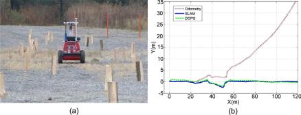
Fig. 2.26 (a) Autonomous rover on a gravel test site with obstacles (b) Comparison of the estimated path by SLAM, wheel odometry and DGPS (Differential GPS). Figure courtesy of [1]
Unlike in 3D modeling where correlation-based dense stereo matching is typically performed, feature-based matching is sufficient for visual odometry and SLAM; indeed, it is preferable for real-time robotics applications, as it is computationally less expensive. Such features are used for localization and a feature map is built at the same time.
The MERs Opportunity and Spirit are equipped with visual odometry capability [32]. An update to the rover’s pose is computed by tracking the motion of autonomously-selected terrain features between two pairs of stereo images. It has demonstrated good performance and successfully detected slip ratios as high as 125 % even while driving on slopes as high as 31 degrees.
As SIFT features [28] are invariant to image translation, scaling, rotation, and fairly robust to illumination changes and affine or even mild projective deformation, they are suitable landmarks for robust SLAM. When the mobile robot moves around in an environment, landmarks are observed over time but from different angles, distances or under different illumination. SIFT features are extracted and matched between the stereo images to obtain 3D SIFT landmarks which are used for indoor SLAM [49] and for outdoor SLAM [1]. Figure 2.26 shows a field trial of an autonomous vehicle at a gravel test site with obstacles and a comparison of rover localization results. It can be seen that the vision-based SLAM trajectory is much better than the wheel odometry and matches well with the Differential GPS (DGPS).
Monocular visual SLAM applications have been emerging in recent years and these only require a single camera. The results are up to a scale factor, but can be scaled with some prior information. MonoSLAM [14] is a real-time algorithm which can recover the 3D trajectory of a monocular camera, moving rapidly through a previously unknown scene. The SLAM methodology is applied to the vision domain of a single camera, thereby achieving real-time and drift-free performance not offered by other structure from motion approaches.
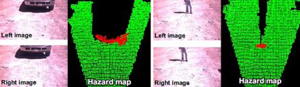
Apart from localization, passive 3D imaging systems can also be used for obstacle/hazard detection in mobile robotics. Stereo cameras are often used as they can recover the 3D information without moving the robot. Figure 2.27 shows the stereo
88 |
S. Se and N. Pears |
Fig. 2.27 Examples of hazard detection using stereo images: a truck (left) and a person (right)
images and the hazard maps for a truck and a person respectively. Correlation-based matching is performed to generate a dense 3D point cloud. Clusters of point cloud that are above the ground plane are considered as hazards.
2.10 Passive Versus Active 3D Imaging Systems
Before concluding, we briefly compare passive multiple-view 3D imaging systems and their active imaging counterpart, as a bridge between this and the following chapter. Passive systems do not emit any illumination and only perceive the ambient light reflected from the scene. Typically this is reflected sunlight when outdoors, or the light reflected from standard room lighting when indoors. On the other hand, active systems include their own source of illumination, which has two main benefits:
•3D structure can be determined in smooth, textureless regions. For passive stereo, it would be difficult to extract features and correspondences in such circumstances.
•The correspondence problem either disappears, for example a single spot of light may be projected at any one time, or is greatly simplified by controlling the structure of the projected light.
The geometric principle of determining depth from a light (or other EMR) projector (e.g. laser) and a camera is identical to the passive binocular stereo situation. The physical difference is that, instead of using triangulation applied to a pair of back-projected rays, we apply triangulation to the axis of the projected light and a single back-projected ray.
Compared with active approaches, passive systems are more computationally intensive as the 3D data is computed from processing the images and matching image features. Moreover, the depth data could be noisier as it relies on the natural texture in the scene and ambient lighting condition. Unlike active scanning systems such as laser scanners, cameras could capture complete images in milliseconds, hence they can be used as mobile sensors or operate in dynamic environments. The cost, size, mass and power requirements of cameras are generally lower than those of active sensors.