Материал: 2048

The rotating magnetic field in the stator coils, in addition to inducing voltages in the rotor bars, also induces voltages in the stator and rotor cores. The voltages in these cores cause small currents, called eddy currents, to flow. The eddy currents serve no useful purpose and result in wasted power. To keep these currents to a minimum, the stator and rotor
Сcores are made of thin steel discs called laminations. These laminations are
coated with insulating varnish and then edge welded together to form a core. This type of core construction substantially reduces eddy current losses, but does not entirely eliminate them.
By varying the design of the basic squirrel-cage motor, almost any characteristic of speed, torque, and voltage can be controlled by the designer. To standardize motor features the National Electrical Manufacturers Association (NEMA) has established standards for a number of motor fea-
tures. |
бА |
||||
|
|
|
|
|
|
The speed of an ac induction motor depends on the frequency of the supply |
|||||
voltageиand the number of poles for which the motor is wound. The term |
|||||
“poles” refers to the manner in which the stator coils are connected to the |
|||||
three incoming power leads to create the desired rotating magnetic field. |
|||||
Motors are always wound with an even number of poles. The higher the |
|||||
input frequency, the faster the motor runs. The more poles a motor has, the |
|||||
slower it runs at a given input frequency. The synchronous speed of an ac |
|||||
induction motor is the speed at which the stator magnetic flux rotates |
|||||
|
|
|
Д |
||
around the stator core at the air gap. At 60 Hz the following synchronous |
|||||
speeds are obtained: |
|
|
|
||
|
|
Number of poles |
RPM |
|
|
|
|
2 |
|
3,600 |
|
|
|
4 |
|
И |
|
|
|
|
1,800 |
|
|
|
|
6 |
|
1,200 |
|
|
|
8 |
|
900 |
|
|
|
10 |
|
720 |
|
|
|
12 |
|
600 |
|
Providing the motor is properly constructed, the output speed can be doubled for a given number of poles by running an ASD supplying the motor at an output frequency of 120 Hz. The actual speed of an induction motor rotor and shaft is always somewhat less than its synchronous speed. The difference between the synchronous and actual speed is called slip. If the rotor rotated as fast as the stator magnetic field, the rotor conductor
81
bars would appear to be standing still with respect to the rotating field. There would be no voltage induced in the rotor bars and no current would be set up to produce torque. Induction motors are made with slip ranging from less than 5% up to 20%. A motor with a slip of 5% or less is known as a normal-slip motor. A normal-slip motor is sometimes referred to as a
С'constant speed' motor because the speed changes very little from no-load to full-load conditions. A common four-pole motor with a synchronous speed of 1,800 rpm may have a no-load speed of 1,795 rpm and a full-load speed of 1,750 rpm. The rate-of-change of slip is approximately linear fromи10% to 110% load, when all other factors such as temperature and voltage are held constant. Motors with slip over 5% are used for hard to start applications.
The direction of rotation of a poly-phase ac induction motor depends on the connectionбАof the stator leads to the power lines. Interchanging any two input leads reverses rotation.
MAGNETIC MOTOR STARTERS
The magnetic motor starter is a magnetic contactor with an overload protection device. Unlike the fuse, the magnetic motor starter does not have to be replaced. It can be reset repeatedly.
Д Рис. 16 И
THE MOTOR CIRCUITS
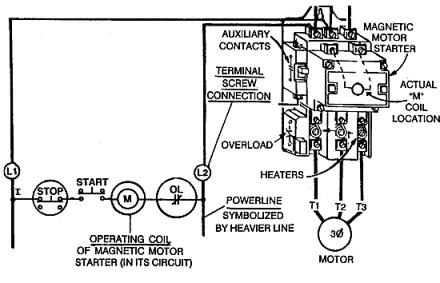
Larger current-demanding motors use two circuits for operation. One circuit is the three-phase power circuit supplied from the distribution power panel. The other electrical circuit is the control circuit. The figure shows the magnetic motor starter and the power circuit from the distribution power panel. The heavy, dark lines provide the three-phase, high current-carrying power to the motor.
82
СиРис. 17
Inside the magnetic motor starter, directly under the coil, are three large main contact sets. These contacts are in series with the power panel A, B, and C phase terminals and the T1, T2, and T3 motor terminals. As long as these contacts are closed, current from the power distribution panel can operate the motor. This is one circuit.
The other circuit controls the three large contact sets explained |
|
above. The coil in Figure 1 actually moves the contacts. The figure shows |
|
|
Д |
the control circuit that the coil is actually in. M represents the coil in the |
|
figure. |
бА |
The M coil is supplied single-phase power from the magnetic motor start- |
|
ers A and B phase terminals (also known as L1 and L2 terminals). The
figure above shows two M coils: one in its true physical position in the И
magnetic motor starter and the other in the line diagram to explain its function electrically. There is actually only one M coil. The same applies to the NC overload contacts.
When the START button is pressed, a complete circuit from A phase through the M coil, through the NC overload contacts, to the B phase is
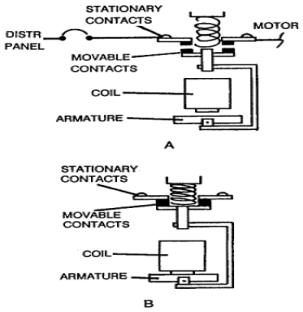
completed in the control circuit. The M coil energizes and moves a bar, known as an armature, that is in physical contact with the three large power contacts in the motor's three-phase power circuit. The figure below illustrates this action.
83
С |
|
и |
Рис. 18 |
|
|
The main power circuit contacts for the motor are held open by |
|
spring tension. When the coil becomes energized, the magnetic attraction |
|
between the armature and the magnet overcomes spring tension, and the |
|
main contacts for the motor close. The motor now operates. |
|
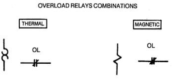
When the current to the motor is too great, the overload heaters get |
|
hot. The heatersбАare in series with the motor terminals and the main contacts for the motor. The heaters directly control what happens to the NC overload contacts in the control circuit. When the heaters get hot enough, the overload contacts open, and the M coil de-energizes. The loss of the magnetic field allows spring pressure to open the three main contacts in series with the motor, and the motor stops operating. By de-energizing the one coil (M), all three sets of main contacts open. Detrimental single phas-
ing is avoided. |
Д |
|
|
A minor disadvantage of the thermal overload device is its need to |
|
cool off before being reset. The Figure shows a magnetic motor starter and |
|
the overload heater and NC overload contact section separately. |
|
|
И |
84
BTU THYRISTOR AMPLIFIER UNIT
С |
|
и |
|
бА |
|
|
Рис. 19 |
1. Purpose
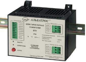
1.1. The BTU thyristor amplifier unit (hereinafter referred to as the "device") built around a solid-state semiconductor optronic three-phase relay is intended for switching of a single– or three-phase voltage applied to an electrical drive of an actuating mechanism. The "Open", "Close" and "Interlock" discrete inputs of the device, which perform control functions, are intended for operation with circuits consisting of "dry contacts" and do not call for additional power sources.ДThe device has a discrete output to indicate current overload in the form of a normally open "dry contact". The device monitors current consumption of the electrical drive across phases B and C. In case of emergency or when the protection circuitry becomes
1.2.1.Nominal values of climatic factors – accordingИto GOST 15150 for the UKhL4 climatic version and atmosphere type II (industrial).
1.2.2.The device protection level is IP20 according to GOST 14254 (protection against getting of foreign solid bodies of more than 12.5 mm in diameter).
2. Specifications
2.1. The device characteristics are as follows:
– the number of discrete inputs to connect external control – three;
85