Материал: BUL147RE
BUL147 |
BUL147F |
|
|
5 |
|
|
VCE |
|
|
4 |
|
|
3 |
dyn 1 μs |
|
2 |
dyn 3 μs |
|
|
|
VOLTS |
1 |
|
0 |
|
|
±1 |
|
|
|
|
|
|
±2 |
90% IB |
|
|
|
|
±3 |
1 μs |
|
±4 |
3 μs |
|
IB |
|
|
±5 |
|
|
|
TIME |
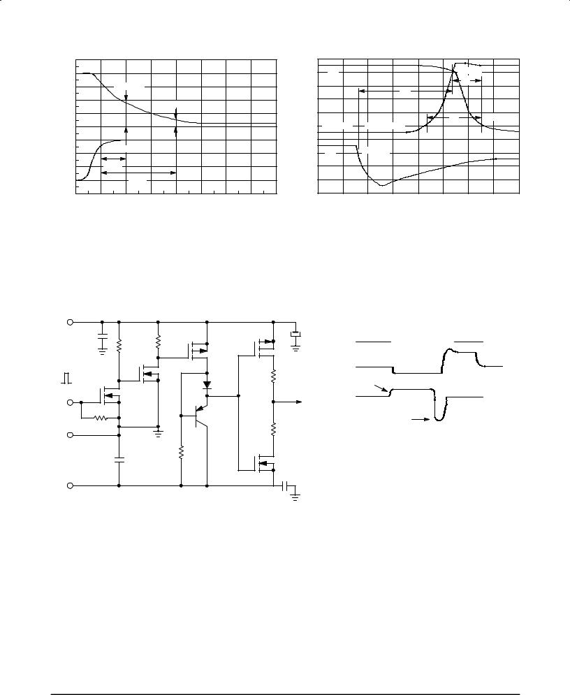
Figure 18. Dynamic Saturation Voltage Measurements
10 |
|
|
|
|
|
|
|
|
9 |
IC |
|
|
|
|
90% IC |
|
|
8 |
|
|
|
|
|
tfi |
|
|
|
|
tsi |
|
|
|
|
|
|
7 |
|
|
|
|
|
|
|
|
|
|
|
|
|
|
|
|
|
6 |
|
|
|
|
tc |
|
10% IC |
|
5 |
VCLAMP |
10% VCLAMP |
|
|
|
|||
|
|
|
|
|
||||
4 |
|
|
|
|
|
|
|
|
3 |
IB |
90% IB1 |
|
|
|
|
|
|
2 |
|
|
|
|
|
|
|
|
1 |
|
|
|
|
|
|
|
|
0 |
|
|
|
|
|
|
|
|
0 |
1 |
2 |
3 |
4 |
5 |
6 |
7 |
8 |
|
|
|
|
TIME |
|
|
|
|
Figure 19. Inductive Switching Measurements
+15 V |
|
|
|
|
|
|
|
|
|
1 |
μF |
|
100 |
Ω |
|
MTP8P10 |
|
100 μF |
|
|
|
|
|
|
|||||
|
150 Ω |
|
|
|
|
|
|||
|
3 W |
|
|
|
|
|
|
||
|
3 W |
|
|
|
|
|
|
|
|
|
|
|
|
|
|
|
|
|
|
|
MPF930 |
|
|
|
|
MTP8P10 |
RB1 |
|
VCE |
|
|
|
|
|
MUR105 |
|
IB1 |
||
|
MPF930 |
|
|
|
Iout |
||||
+10 V |
|
|
|
|
I |
||||
|
|
|
|
|
|
|
|
|
B |
|
|
|
|
|
|
|
A |
|
|
|
50 Ω |
|
|
|
|
MJE210 |
RB2 |
|
|
|
|
|
|
|
|
|
|
||
|
|
|
|
|
|
|
|
V(BR)CEO(sus) |
|
COMMON |
|
|
|
|
150 Ω |
MTP12N10 |
|
|
|
|
|
|
|
|
|
|
L = 10 mH |
||
|
|
|
|
|
|
|
|
||
|
500 |
μ |
F |
|
3 W |
|
|
|
RB2 = ∞ |
|
|
|
|
|
|
|
VCC = 20 VOLTS |
||
|
|
|
|
|
|
|
|
|
|
|
|
|
|
|
|
|
1 |
μ |
IC(pk) = 100 mA |
|
|
|
|
|
|
|
F |
|
|
±Voff
 IC PEAK
VCE PEAK 
IB2 |
|
INDUCTIVE SWITCHING |
RBSOA |
L = 200 μH |
L = 500 μH |
RB2 = 0 |
RB2 = 0 |
VCC = 15 VOLTS |
VCC = 15 VOLTS |
RB1 SELECTED FOR |
RB1 SELECTED |
DESIRED IB1 |
FOR DESIRED IB1 |
Table 1. Inductive Load Switching Drive Circuit
3±6 |
Motorola Bipolar Power Transistor Device Data |
BUL147 BUL147F
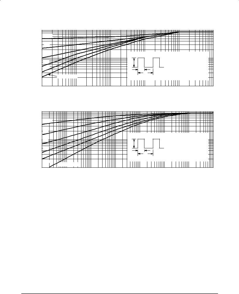
TYPICAL THERMAL RESPONSE
|
|
1 |
|
|
|
|
|
TRANSIENT THERMAL RESISTANCE |
|
D = 0.5 |
|
|
|
|
|
|
0.2 |
|
|
|
|
|
|
(NORMALIZED) |
0.1 |
|
|
P(pk) |
RθJC(t) = r(t) RθJC |
|
|
0.1 |
|
|
|
RθJC = 1.0°C/W MAX |
|
||
0.05 |
|
|
|
D CURVES APPLY FOR POWER |
|
||
0.02 |
|
|
t1 |
PULSE TRAIN SHOWN |
|
||
|
|
|
READ TIME AT t1 |
|
|||
|
SINGLE PULSE |
|
t2 |
TJ(pk) ± TC = P(pk) RθJC(t) |
|
||
|
|
DUTY CYCLE, D = t1/t2 |
|
||||
r(t), |
|
|
|
|
|
|
|
|
|
0.01 |
|
|
|
|
|
|
|
0.01 |
0.1 |
1 |
10 |
100 |
1000 |
t, TIME (ms)
Figure 20. Typical Thermal Response (ZθJC(t)) for BUL147
|
|
1 |
|
|
|
|
|
|
|
|
TRANSIENT THERMAL RESISTANCE |
|
|
D = 0.5 |
|
|
|
|
|
|
|
(NORMALIZED) |
|
0.2 |
|
|
|
|
|
|
|
|
0.1 |
|
|
|
|
P(pk) |
|
RθJC(t) = r(t) RθJC |
|
||
0.1 |
|
|
|
|
|
° |
|
|||
|
|
|
|
|
|
RθJC = 2.78 C/W MAX |
|
|||
|
|
|
|
|
|
|
D CURVES APPLY FOR POWER |
|
||
|
0.05 |
|
|
|
t1 |
|
PULSE TRAIN SHOWN |
|
||
|
|
|
|
|
t2 |
READ TIME AT t1 |
|
|||
|
|
|
|
|
|
TJ(pk) ± TC = P(pk) RθJC(t) |
|
|||
|
|
|
|
|
DUTY CYCLE, D = t1/t2 |
|
||||
r(t), |
|
|
0.02 |
|
|
|
|
|
||
|
|
SINGLE PULSE |
|
|
|
|
|
|
||
|
|
|
|
|
|
|
|
|
||
|
|
0.01 |
|
|
|
|
|
|
|
|
|
|
|
|
|
|
|
|
|
|
|
|
|
0.01 |
0.1 |
1 |
10 |
100 |
1000 |
10000 |
100000 |
|
t, TIME (ms)
Figure 21. Typical Thermal Response (ZθJC(t)) for BUL147F
Motorola Bipolar Power Transistor Device Data |
3±7 |
BUL147 BUL147F
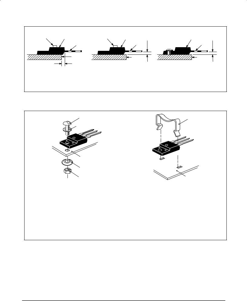
TEST CONDITIONS FOR ISOLATION TESTS*
|
MOUNTED |
|
MOUNTED |
|
MOUNTED |
|
|
CLIP |
FULLY ISOLATED |
CLIP |
FULLY ISOLATED |
0.107″ MIN |
FULLY ISOLATED |
0.107″ MIN |
|
PACKAGE |
PACKAGE |
PACKAGE |
|||||
|
|
LEADS |
LEADS |
HEATSINK |
HEATSINK |
0.110″ MIN |
|
LEADS
HEATSINK |
Figure 22a. Screw or Clip Mounting Position |
Figure 22b. Clip Mounting Position |
Figure 22c. Screw Mounting Position |
for Isolation Test Number 1 |
for Isolation Test Number 2 |
for Isolation Test Number 3 |
* Measurement made between leads and heatsink with all leads shorted together.
MOUNTING INFORMATION**
4±40 SCREW |
CLIP |
PLAIN WASHER
HEATSINK |
|
COMPRESSION WASHER |
|
NUT |
HEATSINK |
|
|
Figure 23a. Screw±Mounted |
Figure 23b. Clip±Mounted |
Figure 23. Typical Mounting Techniques
for Isolated Package
Laboratory tests on a limited number of samples indicate, when using the screw and compression washer mounting technique, a screw torque of 6 to 8 in . lbs is sufficient to provide maximum power dissipation capability. The compression washer helps to maintain a constant pressure on the package over time and during large temperature excursions.
Destructive laboratory tests show that using a hex head 4±40 screw, without washers, and applying a torque in excess of 20 in . lbs will cause the plastic to crack around the mounting hole, resulting in a loss of isolation capability.
Additional tests on slotted 4±40 screws indicate that the screw slot fails between 15 to 20 in . lbs without adversely affecting the package. However, in order to positively ensure the package integrity of the fully isolated device, Motorola does not recommend exceeding 10 in . lbs of mounting torque under any mounting conditions.
** For more information about mounting power semiconductors see Application Note AN1040.
3±8 |
Motorola Bipolar Power Transistor Device Data |
BUL147 BUL147F
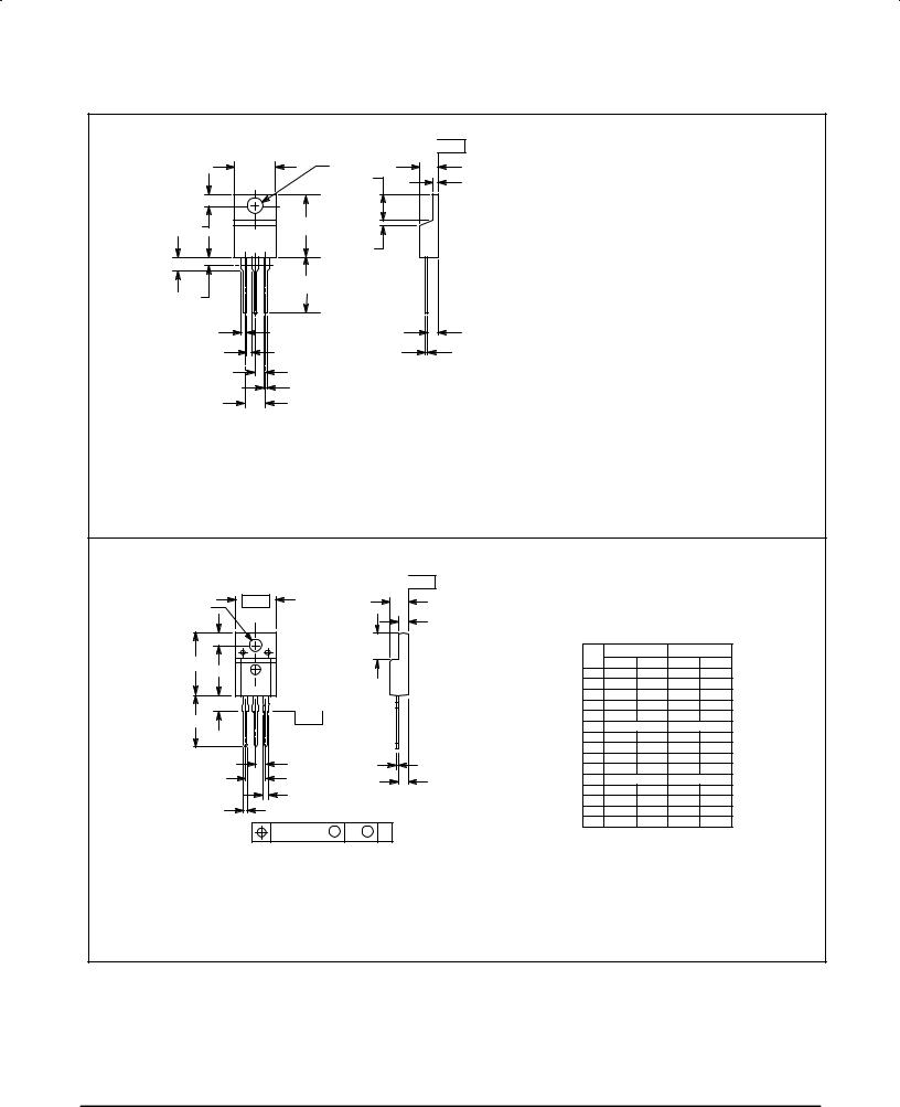
PACKAGE DIMENSIONS
|
|
|
|
±T± |
PLANESEATING |
|
B |
|
F |
C |
|
|
|
|
T |
S |
|
4 |
|
|
|
|
|
Q |
|
|
A |
|
|
1 |
2 |
3 |
U |
|
|
H |
|
|
|
|
|
Z |
|
|
K |
|
|
|
|
|
|
|
|
|
STYLE 1: |
|
L |
R |
PIN 1. |
|
2. |
|||
|
|
||
V |
J |
3. |
|
4. |
|||
|
|
||
G |
|
|
|
|
D |
|
|
|
N |
|
NOTES:
1.DIMENSIONING AND TOLERANCING PER ANSI Y14.5M, 1982.
2.CONTROLLING DIMENSION: INCH.
3.DIMENSION Z DEFINES A ZONE WHERE ALL BODY AND LEAD IRREGULARITIES ARE ALLOWED.
|
|
INCHES |
MILLIMETERS |
||
|
DIM |
MIN |
MAX |
MIN |
MAX |
|
A |
0.570 |
0.620 |
14.48 |
15.75 |
|
B |
0.380 |
0.405 |
9.66 |
10.28 |
|
C |
0.160 |
0.190 |
4.07 |
4.82 |
|
D |
0.025 |
0.035 |
0.64 |
0.88 |
|
F |
0.142 |
0.147 |
3.61 |
3.73 |
|
G |
0.095 |
0.105 |
2.42 |
2.66 |
|
H |
0.110 |
0.155 |
2.80 |
3.93 |
|
J |
0.018 |
0.025 |
0.46 |
0.64 |
|
K |
0.500 |
0.562 |
12.70 |
14.27 |
BASE |
L |
0.045 |
0.060 |
1.15 |
1.52 |
COLLECTOR |
N |
0.190 |
0.210 |
4.83 |
5.33 |
EMITTER |
Q |
0.100 |
0.120 |
2.54 |
3.04 |
COLLECTOR |
R |
0.080 |
0.110 |
2.04 |
2.79 |
|
S |
0.045 |
0.055 |
1.15 |
1.39 |
|
T |
0.235 |
0.255 |
5.97 |
6.47 |
|
U |
0.000 |
0.050 |
0.00 |
1.27 |
|
V |
0.045 |
±±± |
1.15 |
±±± |
|
Z |
±±± |
0.080 |
±±± |
2.04 |
BUL44
CASE 221A±06
TO±220AB
ISSUE Y
|
|
|
|
|
±T± |
SEATING |
|
|
|
|
|
|
|
|
|
|
|
|
|
PLANE |
|
|
|
|
|
|
|
±B± |
|
|
C |
|
|
NOTES: |
|
|
|
|
|||
F |
|
|
|
|
S |
|
1. DIMENSIONING AND TOLERANCING PER ANSI |
||||||
|
|
|
|
|
|
|
Y14.5M, 1982. |
|
|
|
|||
Q |
|
|
|
|
|
|
|
2. |
CONTROLLING DIMENSION: INCH. |
|
|||
|
|
|
|
U |
|
|
|
|
|
|
|
|
|
|
|
|
|
|
|
|
|
|
INCHES |
MILLIMETERS |
|||
|
|
|
|
|
|
|
|
|
|
||||
A |
|
|
|
|
|
|
|
|
DIM |
MIN |
MAX |
MIN |
MAX |
|
|
|
|
|
|
|
|
|
A |
0.621 |
0.629 |
15.78 |
15.97 |
1 |
2 |
3 |
|
|
|
|
|
|
B |
0.394 |
0.402 |
10.01 |
10.21 |
|
|
|
|
|
|
C |
0.181 |
0.189 |
4.60 |
4.80 |
|||
H |
|
|
|
|
|
|
|
|
|||||
|
±Y± |
|
|
|
STYLE 2: |
|
|
D |
0.026 |
0.034 |
0.67 |
0.86 |
|
K |
|
|
|
|
PIN 1. |
BASE |
|
F |
0.121 |
0.129 |
3.08 |
3.27 |
|
|
|
|
|
|
2. |
COLLECTOR |
|
G |
0.100 BSC |
2.54 BSC |
|||
|
|
|
|
|
|
|
|||||||
|
|
|
|
|
|
3. |
EMITTER |
|
H |
0.123 |
0.129 |
3.13 |
3.27 |
|
|
|
|
|
|
|
|
|
J |
0.018 |
0.025 |
0.46 |
0.64 |
|
|
G |
|
|
J |
|
|
|
K |
0.500 |
0.562 |
12.70 |
14.27 |
|
|
|
|
|
|
|
L |
0.045 |
0.060 |
1.14 |
1.52 |
||
|
|
N |
|
|
|
R |
|
|
N |
0.200 BSC |
5.08 BSC |
||
|
|
L |
|
|
|
|
|
Q |
0.126 |
0.134 |
3.21 |
3.40 |
|
|
|
|
|
|
|
|
|
||||||
|
|
|
|
|
|
|
|
R |
0.107 |
0.111 |
2.72 |
2.81 |
|
|
|
D 3 PL |
|
|
|
|
|
|
|||||
|
|
|
|
|
|
|
|
S |
0.096 |
0.104 |
2.44 |
2.64 |
|
|
|
0.25 (0.010) M |
B |
M |
Y |
|
|
|
U |
0.259 |
0.267 |
6.58 |
6.78 |
|
|
|
|
|
|
|
|
|
|
||||
BUL44F
CASE 221D±02
(ISOLATED TO±220 TYPE)
ISSUE D
Motorola Bipolar Power Transistor Device Data |
3±9 |

BUL147 BUL147F
Motorola reserves the right to make changes without further notice to any products herein. Motorola makes no warranty, representation or guarantee regarding the suitability of its products for any particular purpose, nor does Motorola assume any liability arising out of the application or use of any product or circuit, and specifically disclaims any and all liability, including without limitation consequential or incidental damages. ªTypicalº parameters can and do vary in different applications. All operating parameters, including ªTypicalsº must be validated for each customer application by customer's technical experts. Motorola does not convey any license under its patent rights nor the rights of others. Motorola products are not designed, intended, or authorized for use as components in systems intended for surgical implant into the body, or other applications intended to support or sustain life, or for any other application in which the failure of the Motorola product could create a situation where personal injury or death may occur. Should Buyer purchase or use Motorola products for any such unintended or unauthorized application, Buyer shall indemnify and hold Motorola and its officers, employees, subsidiaries, affiliates, and distributors harmless against all claims, costs, damages, and expenses, and reasonable attorney fees arising out of, directly or indirectly, any claim of personal injury or death associated with such unintended or unauthorized use, even if such claim alleges that Motorola was negligent regarding the design or manufacture of the part. Motorola and  are registered trademarks of Motorola, Inc. Motorola, Inc. is an Equal Opportunity/Affirmative Action Employer.
How to reach us: |
|
USA / EUROPE: Motorola Literature Distribution; |
JAPAN: Nippon Motorola Ltd.; Tatsumi±SPD±JLDC, Toshikatsu Otsuki, |
P.O. Box 20912; Phoenix, Arizona 85036. 1±800±441±2447 |
6F Seibu±Butsuryu±Center, 3±14±2 Tatsumi Koto±Ku, Tokyo 135, Japan. 03±3521±8315 |
MFAX: RMFAX0@email.sps.mot.com ± TOUCHTONE (602) 244±6609 HONG KONG: Motorola Semiconductors H.K. Ltd.; 8B Tai Ping Industrial Park, |
|
INTERNET: http://Design±NET.com |
51 Ting Kok Road, Tai Po, N.T., Hong Kong. 852±26629298 |
◊ BUL147/D
*BUL147/D*