Материал: Russian Journal of Building Construction and Architecture
Issue № 1 (41), 2019 |
ISSN 2542-0526 |
Low deposition of underground waters causes porous water to come into the upper part of a base foundation. For negative Celsius temperatures this water freezes and it goes from liquid to solid accompanied by forces of frosty swelling [15] that result in the failure of roadway surfacing.
In order to dry water-saturated soil, the upper part of a drowned slope is drained using highporous sand and gravel drains [5] and anti-filtration screens [13], oil waste hydrophobisators, preventing water migration in the freezing zone [15]. In [12] there is a suggestion for water drainage systems using draining pipes.
A high-speed solution for calculating the parameters of drainage systems is achieved by mathematical modeling of water transfer in a porous motorway foundation. There are also papers that deal with modeling in porous media [1, 9, 11, 17]. In [16] a mathematical modeling describing an improbable imbalanced heat and thermal transfer in a three-dimensional porous medium is set forth.
There are methods of mathematical modeling of filtration in soils considering film humidity transfer [6], evaporation from its free surface [2], horizontal filtration increasing as does the depth of underground water [19], non-stationary vertical filtration based on the Fokker-Planck equation [18] based on vertical capillary cylinders [20].
In the present paper a mathematical model is suggested that allows only for vertical filtration and major typical porosity of soils, an accurate solution for the equation of the humidity transfer and the way it could be applied for calculating a drainage system.
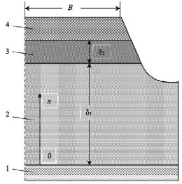
1. Statement of the problem. The Figure presents a scheme of a road foundation that is a porous medium. The humidity ure transfer of underground water is presented which is a porous medium. The humidity ure transfer of underground water in the vertical direction occurs under the effect of capillary forces and gravity.
Fig. Scheme for calculating humidity ure transfer of underground water in a motorway foundation:
1 is underground water;
2 is a soil foundation;
3 is a draining layer;
4 is roadway surfacing
85

Russian Journal of Building Construction and Architecture
In this case a differential equation of humidity ure transfer, which is a particular case of the movement equation presented in [16] takes the following form:
1 |
u du |
|
u g, |
|
|
m2 |
(1) |
||||
dx |
|
k |
where m=Vpor/V is the porosity of the soil; k is the coefficient of the penetrability of the soil that has a dimensional area; x is the coordinate calculated from the vertical up to the underground water level; u is a projection of the water lifting rate up to the axis x; ν is a kinematic viscosity of water; g is the free fall acceleration. In engineering calculations of water penetrability of soils the filtration coefficient is employed
Кф gk |
, |
(2) |
|
|
characterizing the filtration rate related to a dimensionless pumping gradient [3]. We transform the equation (1):
du2 |
2m |
2 |
|
|
, |
|||
|
dx |
|
|
u g |
||||
|
|
|
k |
|
(3) |
|||
|
|
|
|
|
|
|
|
|
by integrating it |
|
|
|
|
|
|
|
|
u |
|
|
|
du2 |
|
2m2 x dx. |
||
|
|
|
u g |
|
||||
0 |
|
|
0 |
|
||||
|
|
|
|
|
|
|||
|
|
k |
|
|
|
|
|
|
(4)
we get an accurate solution:
u ug u m 2g x m2 x k , |
(5) |
|
where uσ and ug are the humidity transfer rates in a porous soil only under the effect of capillary forces and gravity.
An extremum study of the function (5) shows that the rate of water lifting along the height of the soil level is not stable and changes from zero to the underground water level up to the maximum at
x 2gk 2 m2 2 ,
and then drops down to zero. The maximum and average length in the range of a layer with the thickness δ of the rate is given by the ratios
|
|
umax gk |
2 , |
(6) |
|
|
|
|
|
|
|
|
1 |
|
2m |
2g m2 . |
|
uср |
udx |
(7) |
|||
|
|
0 |
3 |
2k |
|
86

Issue № 1 (41), 2019 |
ISSN 2542-0526 |
For a multi-layer structure of a motorway foundation along the height the local rates at the contact boundaries are equal. Therefore the distribution of the water lifting rate in the i-th layer is determined with the formula:
|
|
n |
|
|
m2 |
|
n |
|
|
|
ui 1 ui mi |
2g x i |
|
i |
|
x i |
, |
||||
ki |
|
|||||||||
|
|
i 1 |
|
|
|
|
i 1 |
|
(8) |
|
|
|
|
|
|
|
|
|
|
|
|
where i is the number of the layer, i = 1, 2, …, n; n is the number of the layers of the thickness δi with homogeneous porosity along the height of a motorway foundation.
The complete water consumption ρ in any layer of a motorway foundation for one running meter of a motorway with the halfwidth B (Fig.) is given by the formula
(9) 2. The results of the calculation analysis. Let us look at the example of calculating humidity transfer for three types of homogeneous subbase foundation with varying penetrability for fixed halfwidths of a roadway B = 10 m and thermal and physical properties of water: ν = 10−6 m2/sec; ρ = 103 kg/m3.
The tables shows that the maximum water filtration rate (6) is the same as the filtration coefficient, which proves that the calculation analysis based on the solution of the movement equation is viable (1).
|
|
|
|
|
Таble |
|
|
|
|
|
|
|
|
|
Characteristics of porosity and penetrability |
|
|
|||
Type of soil |
|
of soil |
|
umax, m/sec |
G, kg/(m∙seс) |
|
|
|
|
||||
m |
Кф, m/day |
k, m2 |
||||
|
|
|
||||
|
|
м/c |
|
|
|
|
|
|
|
|
|
|
|
Coarse crushed stone |
|
1000 |
1.26∙10−9 |
6.3∙10−3 |
63 |
|
with sand |
|
|
|
|
|
|
|
6.3∙10−3 |
|
|
|
||
Penetrable pebbles |
0.65 |
100 |
1.26∙10−10 |
6.3∙10−4 |
6.3 |
|
with fine sand |
|
|
|
|
|
|
|
6.3∙10−4 |
|
|
|
||
Pebbles with sand and clay |
|
10 |
1.26∙10−11 |
6.3∙10−5 |
0.63 |
|
|
6.3∙10−5 |
|
|
|
||
|
|
|
|
|
||
Sand, sandy loam |
|
1 |
1.26∙10−12 |
6.3∙10−6 |
0.063 |
|
|
6.3∙10−6 |
|
|
|
||
|
|
|
|
|
||
3. Calculation of the parameters of a new drainage system. In [12] a new scheme for road drainage in areas with high humidity humidity is suggested which is effective for small deposits of underground water for constantly flooded areas as well as those with a great amount of
87

Russian Journal of Building Construction and Architecture
rainfall and where water is accumulated and coming from the surface submerges roadways. In a drainage layer of a subbase foundation with the filtration coefficient of no less than 1 m/day there are perforated plastic pipes with the diameter d = 70—110 mm filled with coarse crushed stone. The pipes are positioned along the entirety of the road.
If a draining level is not too thick, pipes are positioned horizontally with the distance L between them. These intervals then have to be identified using the conditions of equal water consumption in a subbase foundation and drainage pipes.
The water consumption in a subbase foundation of sand and sandy loam for one running meter of a roadway with the halfwidth B is given by the formula (9):
G |
u |
max |
B 6.3 10 6 |
103 10 6.3 10 2, kg/(m×Seс). |
(10) |
Soil |
|
|
|
|
The mass water consumption per second along a pipe with the diameter d = 0.1 m filled with coarse crushed stone and sand is determined only with capillary forces thus
GPipe umax |
d |
2 |
6.3 10 3 103 3.14 10-2 |
4.9 10-2, Kg/Sec. |
(11) |
|
4 |
|
4 |
|
|
The distance between the drainage pipes is
L GPipe |
GSoil 4.9 10-2 /6.3 10-2 0.8 m. |
(12) |
Conclusions
1.The developed method considering only vertical filtration and the major characteristics of the porosity of soil yields the accurate solution for the humidity transfer equation. The water lifting rate along the height of a soil layer is shown to be unstable and changeable as a maximum is reached along the height of a subbase foundation.
2.The method provides an accurate description of humidity transfer in porous soil and is instrumental in high-speed calculation analysis of the parameters of drainage systems in roadway subbase foundations.
3.The example is provided of the use of the method of evaluating a distance between drainage pipes in a new drainage system from under a roadway foundation that mitigates the negative effects of swelling.
References
1. Barenblatt G. I., Entov V. M., Ryzhik V. M. Dvizhenie zhidkostey i gazov v prirodnykh plastakh [Movement of liquids and gases in natural layers]. Moscow, Nedra Publ., 1984. 212 p.
88
Issue № 1 (41), 2019 |
ISSN 2542-0526 |
2.Bereslavskiy E. N., Aleksandrova L. A., Zakharenkova N. V., Pesterev E. V. Matematicheskoe modelirovanie fil'tratsionnykh techeniy s neizvestnymi granitsami v podzemnoy gidromekhanike [Mathematical modeling of seepage flows with unknown boundaries in an underground fluid mechanics]. Mekhanika zhidkosti i gaza. Vestnik Nizhegorodskogo universiteta im. N. I. Lobachevskogo, 2011, no. 4 (3), pp. 644—646.
3.Boldyrev G. G., Malyshev M. V. Mekhanika gruntov. Osnovaniya i fundamenty (v voprosakh i otvetakh). 4-e izd., pererab. i dop. [Soil mechanics. Bases and foundations (in questions and answers). 4th ed.]. Penza, PGUAS Publ., 2009. 412 p.
4.Trofimov V. T., ed. Gruntovedenie. 6-e izd., dop. i pererab. [Soil science. 6th ed.]. Moscow, Izd-vo MGU, 2005. 1024 p.
5.Dolzhik K., Khmelevska I. Raschetnaya otsenka fil'tratsii nesvyaznykh gruntov [Calculation evaluation of non-cohesive soil filtration]. Osnovaniya, fundamenty i mekhanika gruntov, 2014, no. 5, pp. 2—5.
6.Kashchenko N. M., Malakhovskiy V. S., Semenov V. I., Gritsenko V. A. Matematicheskoe modelirovanie protsessov fil'tratsii vlagi v tyazhelykh gruntakh [Mathematical modeling of moisture filtration processes in heavy soils]. Matematicheskoe modelirovanie. Vestnik Baltiyskogo federal'nogo universiteta im. I. Kanta, 2012, vol. 10, pp. 50—53.
7.Kashchenko N. M., Malakhovskiy V. S., Semenov V. I., Gritsenko V. A. Matematicheskoe modelirovanie protsessov fil'tratsii vlagi v tyazhelykh gruntakh [Mathematical modeling of moisture filtration processes in heavy soils]. Matematicheskoe modelirovanie. Vestnik Baltiyskogo federal'nogo universiteta im. I. Kanta, 2012, vol. 10, pp. 50—53.
8.Kim Khyun Chol. Sovershenstvovanie metodov rascheta glubiny sezonnogo promerzaniya puchinistykh
gruntov zemlyanogo polotna zheleznodorozhnogo puti. Avtoref. diss. kand. tekhn. nauk [Improvement of methods for calculating the depth of seasonal freezing of heaving soils of the railroad tracks. Abstract of diss.]. Novosibirsk, 2013. 24 p.
9.Korolev V. A. [Soil water permeability]. Rossiyskaya geologicheskaya entsiklopediya: v 3 t. T. 1 (A—I) [Russian geological encyclopedia: in 3 vol. Vol. 1 (A––I)]. Saint-Petersburg, VSEGEI Publ., 2010. 211 p.
10.Leybenzon L. S. Dvizhenie prirodnykh zhidkostey i gazov v poristoy srede [Movement of natural liquids and gases in a porous medium]. Leningrad, OGIZ-Gostekhizdat Publ., 1947. 244 p.
11.Masket M. Techenie odnorodnykh zhidkostey v poristoy srede [Flow of homogeneous liquids in a porous medium]. Moscow –– Izhevsk, NITs “Regulyarnaya i khaoticheskaya dinamika”, 2004. 628 p.
12.Trefilov V. A., Zhalko M. E. Ustroystvo vodootvedeniya iz-pod dorozhnogo polotna [Device drainage under the roadway]. Patent RF, no. 151370, 2015.
13.Semashkin K. V., Shestakov V. N. Obosnovanie sposoba obespecheniya ustoychivosti v protsesse ekspluatatsii podtoplennykh dorozhnykh nasypey [Justification of the method of ensuring stability during operation of flooded road embankments]. Vestnik TGASU, 2013, no. 4, pp. 280—290.
14.Sugak V. G., Ovchinkin O. A., Silaev Yu. S., Sugak A. V. Georadarnyy metod obnaruzheniya vodonasyshchennykh sloev grunta s otsenkoy ikh ob"emnoy vlazhnosti [GPR method for detection of watersaturated soil layers with assessment of their volume humidity]. Geofizicheskiy zhurnal, 2014, vol. 36, no. 2, pp. 127—137.
15.Khabibullina I. N., Beshenov M. E., Geleverya T. I. Ispol'zovanie ukreplennykh gruntov dlya ustroystva protivopuchinistykh sloev na avtomobil'nykh dorogakh [The use of reinforced soils for the device of anti-fouling
89