Материал: Russian Journal of Building Construction and Architecture

Russian Journal of Building Construction and Architecture
BUILDING MECHANICS
UDC539.4:624.01
Yu. P. Nazarov1, E. V. Poznyak2
THEORY OF A QUASI-STATIC ANALYSIS OF SPORT GRANDSTANDS UNDER LOADS FROM CONCERTED ACTIONS OF SPECTATORS
Central Research Institute of Building Structures Named after V. A. Kucherenko (Federal State Unitary Enterprise Scientific Research Centre «Construction»)
Russia, Moscow, e-mail: nazarov-dom@mail.ru
1D. Sc. in Engineering, Prof., Member of the Russian National Committee on Theoretical and Applied Mechanics, Council of the Russian Academy of Architecture and Building Sciences,
Head Research Fellow
National Research University «Moscow Power Engineering Institute»
Russia, Moscow, e-mail: PozniakYV@mpei.ru
2PhD in Engineering, Assoc. Prof. of the Dept. of Dynamics and Machinery Performance Named after V. I. Bolotin
Statement of the problem. This paper presents deterministic and stochastic methods for a quasistatic structural calculation of the influence of sporting stands on a semi-sinusoid impulse pulse load of audiences moving concertedly.
Results. Deterministic and probabilistic solutions are obtained for specific concerted load, i. e. by walking and jumping up. The study found a connection between the deterministic and probabilistic approaches. Both of the solutions are tested by calculating in a time domain. A method of the assessment of vibrations is described, which is perceived by an audience in accordance to maximum displacements and accelerations.
Conclusions. This study has shown such features of pulse loads as simultaneous excitation of several forms of oscillations and high dynamic factors. In case of high vibrations it is necessary to evaluate a dynamic comfort level. The results of the study can be useful for updating existing guidelines on loads and impacts.
Keywords: quasi-static analysis, impulse load, sporting stands, human effect on a structure, amplification factors, estimation of a dynamic comfort level.
The study was carried out at the Laboratory for Automatization, Research and Design of the Central Scientific Research Institute for Structures Named after V.A. Kucherenko (Ltd. “Scientific Research Centre Construction”) as part of Scientific Research and Experimental Construction Work ordered by the Federal Autonomous Institution “Federal Centre for Standardization and Technical Evaluation in Construction”.
© Nazarov Yu. P., Poznyak Ye. V., 2017
126
Issue № 4 (36), 2017 |
ISSN 2542-0526 |
Introduction
Modern architectural forms of sport and public cultural constructions, which are suspended or console structures, call for calculations for a new type of dynamic impacts –– human-structure interaction loads.
These impacts are due to synchronous movement of people and can be characterized as lowfrequency periodic surface loads. If eigenfrequencies of stands are close to that of impulses generated by spectators, this might lead to an increased vibration level, degradation of operational criteria and sometimes local damage [9—10, 13, 14].
In order to investigate the impact from spectator movement, there has been an extensive series of experiments and theoretical studies performed abroad [13, 14, 16—21] where the approximation of a dynamic load on a stand was obtained as a sequence of half-sinusoidal impulses:
|
|
|
t |
, |
0 t t |
|
, |
|
K |
p |
G sin |
|
p |
|
|||
F t |
|
|
|
|
|
(1) |
||
|
tp |
|
|
|
|
|||
|
|
|
|
|
tp t Tp , |
|
||
0, |
|
|
|
|
|
|||
where Kp = Fmax / G is an impact factor; Fmax is a peak load; G is the weight of a static spectator load on a stand; tp is a contact period; Tp is an impulse period. The ratio of a contact period tp to a load time Tp is a contact ratio α = tp / Tp, the impulse frequency is fp =1 / Tp. It was experimentally shown that the impulse frequency may vary from 1 to 4 Hz [13, 14, 21].
The approximation (1) is the foundation for guidelines of the UK, Canada, Germany and is illustrated in the Eurocode EN 1991-1-1 [12, 15, 4]. In the guideline BS 6399-1:1996 there is a correspondence of different types of contact ratios and those of spectator actions [5]: the value α = 2/3 corresponds to pedestrian movement and low-rhythmic aerobics, the value α = ½ to rhythmic movement and high-rhythmic the value α = 1/3 to regular jumps and the value α = ¼ to high jumps. The decomposition of the function F(t) into a Fourier series [4] is known:
|
|
|
|
|
2 n |
|
2 n |
|
|
|
2 n |
|
||||||||||
F t G 1 an |
cos |
T |
|
t bn sin |
|
T |
|
t G 1 rn |
sin |
|
t n , (2) |
|||||||||||
|
n 1 |
|
|
|
p |
n 1 |
|
p |
|
|
n 1 |
|
T |
p |
|
|
||||||
|
|
|
|
|
|
|
|
|
|
|
|
|
|
|
|
|||||||
|
|
|
|
|
|
|
|
|
|
|
|
|
|
|
|
|
|
|
|
|
||
where an , bn are the Fourier coefficients at 2n 1, |
an 0, bn 2, in other cases |
|
||||||||||||||||||||
|
an 0.5 |
cos 2n 1 1 |
|
cos 2n 1 1 |
, |
|
|
|
||||||||||||||
|
|
|
|
|
|
|
|
|
|
|
|
|
|
|
|
|
|
|||||
|
|
|
|
2n 1 |
|
|
|
2n 1 |
|
|
|
|
|
|||||||||
|
|
|
|
|
|
|
|
|
|
|
|
|
|
|
|
|||||||
|
bn 0.5 |
sin 2n 1 1 |
|
|
sin 2n 1 1 |
, |
|
|
|
|||||||||||||
|
|
|
|
|
|
|
|
|
|
|
|
|
|
|
|
|
||||||
|
|
|
2n 1 |
|
|
|
|
2n 1 |
|
|
|
|
||||||||||
|
|
|
|
|
|
|
|
|
|
|
|
|
|
|
|
|||||||
rn an2 bn2 , n arctg an  bn .
bn .
127
Russian Journal of Building Construction and Architecture
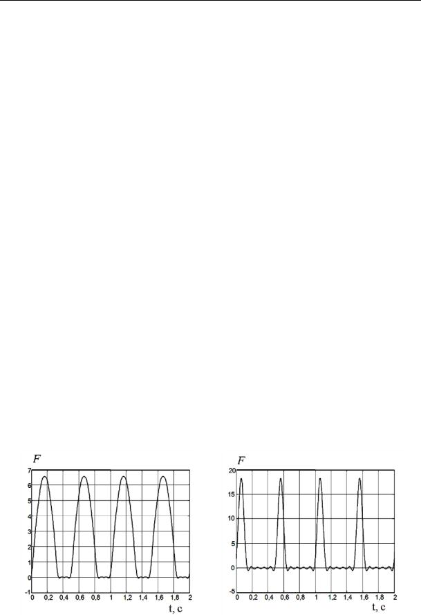
The analysis of the series (2) shows that the impulse load (1) is successfully modeled by the first six harmonics. In Fig. 1 there are graphs of the function F, kN/m2, of the time, sec, obtained by summing the first six harmonics in (2) for α = 2/3 (pedestrian movement) and α = 1/4 (high jumps) with the frequency 2 Hz, a static crowd load is the maximum actual weight 2.80 kN/m2.
A dynamic response of a structure to an impact (1) can be determined in a few ways. The main one is the quasi-statiс method as it is most convenient and known to engineering designers for its common use in seismic resistance. The quasi-static method is convenient as exterior impulse force is applied to a structure as a static load, internal effort does not depend on time, which makes construction calculations easier to perform. Dynamic effects in the quasi-static method are considered using dynamic factors. The quasi-static method can be regarded from the point of view of determined or probabilistic loading [19—21, 12]. In the first case all the parameters of a calculation model and loading are considered strictly prescribed and dynamic factors are determined using the methods of the oscillation theory. In the second case loading is considered as an implementation of a random process and dynamic factors depend on its spectral density. A test calculation will be direct integration of movement equations in a temporary range with the resulting dependencies of the parameters of stress-strain on time. Below are three approaches to solving a dynamic task (a quasi-static determined, quasi-static probabilistic and test in a temporary area) and they are compared. Besides determining a dynamic response, a comfort level is evaluated. Based on the frequencies and amplitudes of vibrodisplacements and vibro-accelerations, 6 gradations of spectators’ perception ranging from “vibrations are not felt” to “vibrations are not pleasant during a short-term impact”.
а) |
b) |
|
|
|
t, sec |
t, sec |
Fig. 1
128
Issue № 4 (36), 2017 |
ISSN 2542-0526 |
1. Movement equations in the main coordinates
The movement equation of a dissipative system with N degrees of freedom takes the following form
Mq+Bq+Cq= P, |
(3) |
where q is a N-dimensional vector of generalized movements; M, B, C are matrices of inertia, damping and solidness of the dimension N×N; P is a N-dimensional vector of generalized external impulse forces. The vector P consists of periodic forces Pi that can be arranged into a Fourier series using the formula (2):
|
|
|
G |
|
NF |
|
2 n |
|
|
|
|
|||||
|
Pi t Pi |
|
1 rn sin |
|
|
|
n |
n , |
|
(4) |
||||||
|
|
|
T |
|
|
|||||||||||
|
|
|
|
|
|
n 1 |
|
|
p |
|
|
|
|
|
||
|
|
|
|
|
|
|
|
|
|
|
|
|
||||
|
|
|
|
|
|
|
|
|
|
|
|
|
|
|||
wherePG |
is a static crowd load along the i-the generalized coordinate; N |
F |
is a number of re- |
|||||||||||||
i |
|
|
|
|
|
|
|
|
|
|
|
|
|
|
|
|
tained members of the Fourier series. As a vector |
|
2 n |
|
|
|
|
|
|
|
|||||||
|
P P |
G |
P |
G |
NF |
|
|
|
|
|
|
|
|
|
||
|
|
|
|
r sin |
|
|
n |
. |
|
|
|
|||||
|
|
|
|
|
|
|
|
|
||||||||
|
|
|
|
|
n |
|
Tp |
|
|
|
n |
|
|
|
||
|
|
|
|
|
n 1 |
|
|
|
|
|
|
|
|
|
||
Let us denote: V is a matrix of eigenvectors of the system (3) of the N×N dimension;
Ω2 diag 2k is a diagonal quadratic matrix of eigenfrequencies; 2k is the square of the k-th eigenfrequency; Mmod is a diagonal modal matrix of the masses:
Mmod VT MV diag Mmod,k ;
Mmod,k is a modal mass along the k-th eigenform; 2ε Mmod1 VT BV is a modal damping matrix. Damping is assumed to be small thus the damping matrix can be considered diagonal ε diag k , k is a modal damping coefficient along the k-th eigenform. Using the transformation q Vuwe obtain a system of independent movement equations in the space of the main coordinates:
u 2εu 2u Q, |
(5) |
where u is a vector of the main coordinates; Q is a vector of external impulse forces reduced to the main coordinates:
Q Mmod1 VT P. In the component-wise form the equation (5) is as follows
u |
2 |
u |
k |
2u |
k |
Q |
, |
(6) |
k |
k |
|
k |
k |
|
|
129
Russian Journal of Building Construction and Architecture
where |
Q |
1 |
vT P; |
|
|||
|
k |
|
k |
|
|
M mod,k |
|
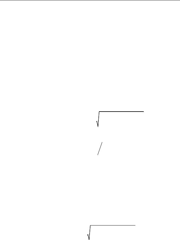
vTk is a vector of the k-th eigenform. The solution in the initial base for the j-th generalized coordinate is
q j vTj u.
2. Quasi-static determined solution
The solution of the equation (5) in an established mode of forced vibrations can be obtained by means of the superposition method considering the decomposition (4) and summing a dynamic response along each harmonic component of a load (the detailed development is provided in [5]):
|
|
|
|
|
|
|
|
|
|
|
|
|
|
|
|
|
|
|
|
|
1 |
|
T |
|
|
|
rn sin n t n |
|
|
|
|
||||||||
|
|
G |
NF |
|
|
|
|
||||||||||||
uk |
|
|
vk |
P 1 |
|
|
|
|
|
|
|
|
|
|
|
|
, |
(7) |
|
2 |
|
|
|
|
|
|
|
|
|
|
|
|
|
||||||
|
k Mmod,k |
|
|
|
n 1 |
|
|
2 |
|
2 |
|
2 |
|
2 k n |
2 |
|
|
||
|
|
|
|
|
|
|
1 n |
|
|
|
|
|
|||||||
|
|
|
|
|
|
|
|
|
|
2 |
|
|
|
|
2 |
|
|
|
|
|
|
|
|
|
|
|
|
k |
|
|
|
|
k |
|
|
|
|
||
where n is a response phase to the n-th harmonic component of a load: |
|
|
|
|
|||||||||||||||
|
n n |
|
|
|
2 n |
|
|
n2 2 |
; |
|
|
|
|
|
|||||
|
arctg |
k 2 |
1 |
|
|
|
2 |
|
|
|
|
|
|
||||||
|
|
|
|
|
k |
|
|
|
k |
|
|
|
|
|
|
|
|||
is an angular frequency of an impulse load:
2 2 f p .
Tp
The summand (7) that is independent of time corresponds to the static movement ust. A maximum dynamic movement along the k-th generalized coordinate u will be found by assuming the sinuses (7) to equal one. Then the modal dynamic factor corresponding to the k-th form of oscillations is
k |
umax,k |
NF |
|
|
|
|
r |
|
|
|
. |
|
1 |
|
|
|
|
|
|
|
|||||
|
|
|
|
|
|
|
n |
|
|
|
|
|
|
ust |
n 1 |
|
1 |
|
n2 2 2 |
|
2 |
n 2 |
|||
|
|
|
|
2 |
|
|
|
k 2 |
|
|||
|
|
|
|
|
|
k |
|
|
k |
|
||
This formula can be written using a modal damping coefficient k ( k k k ) and the frequency expressed in Hz ( fp  2 , fk k
  2 ):
2 ):
130