Материал: Russian Journal of Building Construction and Architecture

Issue № 1(33), 2017 |
ISSN 2542-0526 |
UDC625.7.8
O. A. Sotnikova1
RADIATIVE HEAT EXCHANGE IN HEAT GENERATORS
WITH VORTEX FURNACES
Voronezh State Technical University
Russia, Voronezh, tel.: (473) 277-43-39, e-mail: hundred@vgasu.vrn.ru
1D. Sc. in Engineering, Prof. of the Dept. of Design of Buildings and Structures Named after N. V. Troitsky
Statement of the problem. Vortex motion of smoke gases in a furnace allows one to achieve a uniform temperature distribution within a furnace. Thus processes of heat transfer grow more intense and the reliability of boiler and longevity increases. Vortex principle of burning of fuel leads to rotational speeds, which reduces the expenditure component of the vector of the absolute velocity of smoke gases in the combustion chamber of boilers. Thisin turn leads to a reduction in the heat losses fromchemical and mechanical underburning due to keeping hot gases in a combustion chamber for longer.
Results. An attempt was made to create a vortex furnace of the boiler and the approximate method of its calculation including radiative heat transfer Established in the combustion chamber rotational speeds reduces the expenditure component of the vector of absolute velocity, which leads to an increase in the residence time of hot gases in the combustion chamber and reduce heat loss as chemical and mechanical underburning.
Conclusions. Analytical studies were performed which enabled us to obtain the equations to determine the local angular radiation coefficients of linear source on an elementary area for its different locations: on a horizontal, vertical and inclined heat transfer surface. The analytical expressions are complementary to the known data on the angular radiation coefficients and significantly enhance the radiative heat transfer calculation in the vortex boiler furnaces. The use of vortex burners will allow one to increase the intensity of heat transfer, and increase the longevity of a boiler by providing a uniform temperature distribution within the furnace and to reduce capital and operating costs.
Keywords: radiative heat transfer, angular coefficient of radiation, heat, boiler, vortex furnace, heat exchange, heat transfer.
Introduction
Decentralized and autonomous heat supply typically has relatively short main pipes or none at all, small fuel transportation costs and thus low heat losses and economic efficiency. These systems employ vapour and water-heating boilers. There have been found a few factors that influence the operation in fire chambers.
© Sotnikova О. А., 2017
31

Russian journal of building construction and architecture
Significant thermal losses of a fire chamber call for activities to protect screen surfaces from heating excessively in particular. In practice inside a fire chamber there are local deviations of the temperature with them being as high as a few hudnred degrees. Resulting thermal unevenness are a cause of burnouts and lead to lower efficiency of a chamber. Therefore addressing this problem is currently of importance [1—15].
One of the ways to do that is to apply the whirlwind principle of fuel combustion. It means that using a relevant way of supply in a fire chamber there is a whirl flow of reacting fuel and oxidizer particles.
The twisted shape of a flow in space is reached by a tangential introduction of a fuel-air mix into a chamber. Rotation speeds reduce the consumption of an absolute speed, which results in an increase in how long hot gases stay in a fire chamber and a drop in losses in a chemical and mechanical underburning. A large speed and a high turbulization of a twisted torch cause an increase in the coefficient of gas heat transfer to heated surfaces thus improving the coefficient of efficiency of a chamber.
We have attempted to design a twisted fire chamber and its approximate calculation method as well as for radiative heat exchange. It is mainly used in fire chambers. Heat flows from a gas, fuel, powdered-coal torch contain 85—95 % from a radiative flow and 10—15 % from a convective flow.
1. Determining total integral heat flows and radiation angular coefficients. According to the method by A. N. Makarov [1], total integral heat flows consisting of radiations falling on a heated surface from a torch, wall lining, lid and convective flows. The density of an integral flow falling on the i-th elementary area of a heated surface is determined using the expression
qin qin.ф qin.оф qin.п qin.о.п qiкон , |
(1) |
where qin. t is the density of an integral radiation flow falling on the i-th area from a torch considering the radiation absorption of a torch; qin. оф is the same for a flow generated by the reflection of radiaiton of a torch from the walls, floor and lid; qin. п is the same for a flow of radiating walls, floor, lid considering the reflection and absorption of radiation; qin. о. п is the same for a flow generated by the reflection of radiation from the surfaces of the walls, floor, lid; qiкон is the density of a convective flow per an area.
The most difficult issue with applying this method is determining the angular coefficients. In practice analytical expressions are necessary to identify the angular coefficients of radiation for a cylindrical source (e.g., a torch) and an elementary area in parallel and perpendicular planes.
32
Issue № 1(33), 2017 |
ISSN 2542-0526 |
The properties of constant rad iation of coaxial cylinders suggest that radiaiton of coaxial gas volumes can be substituted by an equivalent radiation of a cylindrical gas volume of a small diameter provided that it radiates power equal to the sum of those of radiation of coaxial cylindrical volumes. A radiating cylinder of a small diameter in thermal physics is traditionally called a linear source of radiation, which will be done further in our calcula tions.
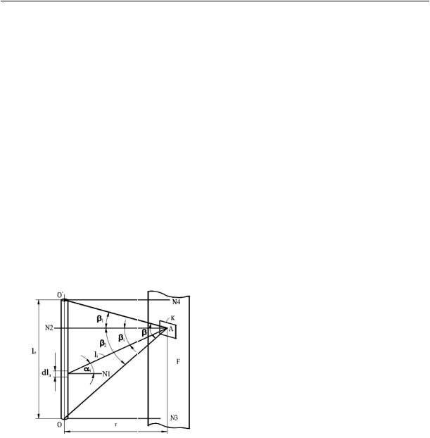
Let us determine a local angular coefficient of radiation of a cylindrical source of radiation on a surface of an elementary area К positioned between the normals N3 and N4 passing through the centre of the upper and lo wer circles of the base of a linear source of radiation (Fig. 1).
2. Geometric design for determining local angular coefficients of radiation for an elementary area on a plane F. An elementary area lies in a plane F parallel to an axis of a cylindrical source of radiation with the height lл. Let us point out an element dlл on the cylindrical source. As a cylindrical linnear source of radiation is a cylinder of an infinitely small diameter, an element dlл is an ele mentary cylinder, i.e. a cylinder of an infinitely small diameter and an infinitely small height dlл.
Fig. 1. Geometric designs for determining local angular coefficients of radiation of a linear source on an elementary area for its position in mutually parallel planes
An elementary angular coefficient of radiation d ik from a surface of an elementary area is given by the expression
d |
|
|
cos i cos iFkdlл |
, |
(2) |
|
ik |
|
|||||
|
|
2l2l |
|
|
|
|
|
|
|
i |
л |
|
|
where i is an angle between a normalN1 to an axis of an elementary cylinder and a direction of radiation, degrees; i is the angle between the normal N2 to the centre of an elementary area and a direction of radiation, degrees; Fk is an area of an elementary area, m2; li is a distance from an elementary cylinder to an elementary area, m.
Let us designate the centre of an elementary area with А, a minimum distance from a point А to an axis of a cylinder with r. Let us draw rays АО and АО′ into the centre of a linear source of
33

Russian journal of building construction and architecture
radiation at a point А. Let us designate an angle between a straight line АN2 and a ray АО′ through 1, an angle between АN2 and a ray АО through 2. As seen from the designs, a linear source radiates into a point А within the angle with = 1 + 2.
A local angular coefficient of radiaiton of a linear source on a surface of an elementary area is given byintegratingthe expression (2) on theheightof a source of radiation:
ik |
cos |
cos F |
|
|||
|
i |
|
i k |
dlл . |
(3) |
|
|
2 |
2 |
|
|||
lл |
|
li |
lл |
|
||
In the expression (3) we have three variables. Using insertion, we will remove two out of three and in addition, integration on the height lл will be replaced by integration on an angle. According to Fig. 1, we have:
i i , cos i cos i , |
(4) |
|
cos i r /li , |
li r /cos i , |
(5) |
dli cos i |
lid . |
(6) |
Inserting (4)—(6) into (3) and integrating on an angle, we get an expression for determining a local angular coefficient of radiation of a linear source of radiation on an elementary area:
lk |
Fk |
|
sin cos( 1 2) , |
(7) |
2 |
|
|||
|
2 rl |
л |
|
|
|
|
|
||
where is an angle at which a linear source radiates on an elementary area, degrees. If an elementary area is positioned in a way that a normal N3 (or N4) passes through a point А, the expression (7) takes the following form:
|
|
Fk |
|
sin cos |
Fk |
|
|
|
1 |
|
|
||
lk |
|
|
|
|
|
|
|
|
|
|
sin2 . |
(8) |
|
2 |
rl |
|
2 |
rl |
|
2 |
|||||||
|
|
2 |
л |
2 |
л |
|
|
|
|||||
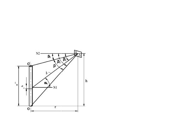
3. Geometric designs for determining local angular coefficients of radiation for an elementary area outside a plane F. In case if an elementary area is positioned outside a projection of a linear source of radiation on a plane F (Fig. 2), the calculation runs as follows.
Let the centre of an elementary area А be positioned at a distance h from a plane that passes through the base of a linear source of radiation with h > lл. An angle at which a linear source radiates on an elementary area is formed with rays АО and АО′ and is . Let us designate an angle between a normal N2 at a point А and a ray АО through 1, an angle between N2 and a ray АО′ through 2.
Fig. 2 suggests that according to the expression (4)—(6), these are appropriate for an elementary area and a linear source of radiation. For determining a local coefficient of radiaiton of a
34
Issue № 1(33), 2017 |
ISSN 2542-0526 |
linear source on an elementary area let us insert (4)—(6) into (2) and integrate the resulting expression within an angle :
lk |
Fk |
|
sin cos( 1 2) . |
(9) |
2 |
|
|||
|
2 rl |
л |
|
|
|
|
|
||
Fig. 2. Geometric designs for determining local angular coefficients of radiation for an elementary area on a vertical plane at a random height
4. Geometric design for determining local angular coefficients of radiation of linear source on an elementary area for their position in mutually perpendicular planes. Let us examine a mutually perpendicular position of planes where there are linear sources of radiation and an elementary area. Let a plane where an elementary area is passes through the base of a linear source of radiation (Fig. 3). Let a shortest distance from a linear source to a point А — r, a normal to the centre of an elementary area be N2, an angle at which a linear source radiates on a point А — ОАО' = . An elementary angular coefficient of radiation dlл on an elementary area is given by the expression (2). A local angular coefficient of radiation of a linear source on an area is identified using integration of the expression (2) on the heig ht of a linear source or after corresponding insertions on an angle β.
Based on Fig. 3, we have:
cos i cos i , |
(10) |
|
li |
r /cos i , |
(11) |
dli |
cos i lid . |
(12) |
Inserting (10)—(12) into (2) and integrating the resulting expression within an angle α, we get an analytical expression for calculating a local angular coefficient of radiaiton of a linear source on an elementary area positioned in a perpendicular plane:
|
|
|
Fk |
|
sin2 . |
(13) |
lk |
2 2rl |
|
||||
|
|
л |
|
|||
|
|
|
|
|
||
35