Материал: Scientific Herald of the Voronezh State University of Architecture and Civil Engineering
Scientific Herald of the Voronezh State University of Architecture and Civil Engineering. Construction and Architecture
The order of joining joints of the node lattice is determined by conditional vectors Vi , i 1,...,m 3 . The coordinates of these vectors are numbers of joints along the ends. The start and end of the vectors are chosen randomly and in no way are they connected with the signs of the efforts in the rods.
For rods of the lower belt we have the following vectors:
Vi [i,i 1], i 1,...,2n ,
for the upper belt:
Vi 2n [i 1 2n,i 2 2n], i 1,..., 2n ,
for racks of lattices: |
|
|
|
|
|
|
|
|
|
|
|
|
|
|
|
|
|
|
|
|||||||||
|
|
|
|
|
|
|
|
|
|
|
|
|
|
|
|
|
|
|
|
|
|
|
|
|
|
|
||
|
|
|
|
|
Vi |
4n |
[i 1,i 2n 1], |
Vi |
4n [i 1,i 2n 2], i 1,...,2n 1, |
|||||||||||||||||||
for braces of lattices: |
|
|
|
|
|
|
|
|
|
|
|
|
|
|
|
|
|
|
|
|||||||||
|
|
|
|
|
|
|
|
|
|
|
|
|
|
|
|
|
|
|
|
|
|
|
|
|
||||
|
|
|
|
Vi |
6n 1 |
[i 2,i 2n 1], |
|
Vi 7n 2 [i n,i 3n 3], |
i 1,..., n 1, |
|||||||||||||||||||
for side racks and braces: |
|
|
|
|
|
|
|
|
|
|
|
|
|
|
|
|||||||||||||
|
|
|
|
|
|
|
|
|
|
|
|
|
|
|
|
|
|
|
||||||||||
|
|
V8n 2 [2,4n 3], V8n 1 [2n,4n 4], |
V8n [2n 3,4n 3], |
V8n 1 [4n 4,4n 1], |
||||||||||||||||||||||||
|
|
|
|
|
|
|
|
|
|
|||||||||||||||||||
V8n 2 [1, 4n 3],V8n 3 [2n 2, 4n 3], |
V8n 4 [4 n 4, 4n 2], V8n 5 [2n 1, 4n 4] . |
|||||||||||||||||||||||||||
The direction cosines which are part of equations of the nodes of a truss are computed using the lengths of rods and projections of their vector presentations on the coordinate axes:
l |
l 2 |
l |
2 |
, |
l |
x |
|
x |
, l |
2,i |
y |
|
y |
|
, i 1,..., m |
0 |
, |
i |
1,i |
|
2,i |
|
1,i |
V |
2,i |
V |
|
V |
2,i |
V |
|
|
|||
|
|
|
|
|
|
|
1,i |
|
|
|
|
1,i |
|
|
|
||
where m0 m 3 is a number of rods of a truss including three rods that correspond with a motionless and non-motionless supports. The first index in the number Vj,i denotes the number of vector component Vi , the second one –– the number of a rod. The matrix of direction cosinesG has the following members:
Gk ,i l j,i / li , k 2Vi,2 2 j, |
k m0 , |
j 1, 2, |
i 1,..., m0 , |
Gk,i l j,i / li , k 2Vi,1 2 j, |
k m0, |
j 1,2, |
i 1,..., m0. |
86

Issue № 1(29), 2016 |
ISSN 2075-0811 |
Identifying the efforts in rods of a truss means solving a system of linear equations which is as follows in the matrix form:
|
|
G |
|
|
|
. |
(1) |
||
S |
B |
||||||||
Here |
|
is a vector of unknown efforts containing three supports; |
|
|
is a vector of loads with |
||||
S |
B |
||||||||
the length m0 . Horizontal loads applied to the node i are written as part of odd members
B2i 1 , vertical ones as part of even B2i . The solution of a system of linear equations are iden-
tified using a reverse matrix S G 1B . This method is well implemented in Maple system [14] and requires no purpose-designed linear algebra software package LinearAlgebra.
The deflection of a central node of the lower belt of a truss is determined using MaxwellMohr formula:
m |
S s l |
|
|
|
k k k |
, |
(2) |
EF |
|||
k 1 |
k |
|
|
where Sk are efforts in the rods of a truss under an external load; sk |
are efforts of a single |
||
load applied to the central node in the middle of a span; lk are lengths of rods. The rod material is assumed to be identical and the modulus of elasticity of all of the rods is E. The
area of a section of the lower belt is assumed to be Fk 2gF0, |
k 1,..., 2n , for the upper |
|
belt Fk 2(1 g)F0, |
k 2n 1,...,4n, lattices (slanting braces |
and racks) — Fk pF0, |
k 4n 1,...,m . A multiplier 0 g 1 that redistributes the area of a section along the lower and upper belt is chosen so that at g 1/ 2, p 1 the areas of the sections of all the rods of a truss are identical and are F0. Let us call the parameter p the coefficient of the reinforcement of the lattice. As g increases, so does the rigidity of the lower belt and that of the upper belt decreases and the total consumption of a material on the belt remains the same.
In order to obtain the formula for deflection, let us use the induction method. Sequentially solving the problem for trusses with 1, 2, 3, etc. panels in the half of the span, let us first of all determine the sequences of whole coefficients proceeding the corresponding expressions and their shared members. We obtain the following
|
a3 (D / g B / (1 g)) (h3H |
n |
c3C |
n |
) / p |
|
|
|
0 (n) P |
n |
n |
|
|
, |
(3) |
||
|
8h2 EF |
|
|
|
|
|||
|
|
0 |
|
|
|
|
|
|
87
Scientific Herald of t he Voronezh State University o f Architecture and Civil Engineering. Construction and Architecture
where |
Bn (27 2n(5n3 |
12n2 4n 36) (24n 27)( 1)n ) /12, |
|
|
C (( )n (n 1) |
1 n 2n2 ) / 2, |
|
|
n |
|
(4) |
|
D (2n2 (4 12n 5n2 ) 3(( 1)n |
||
|
1)) /12, |
||
|
n |
|
|
Hn (3( 1)n (n 1) 3 n 2n2 ) / 2.
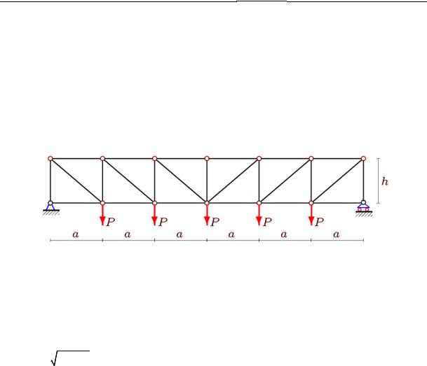
3. Analysis and c omparison. Let us look at a comparison truss 1 (Fig. 2 ) with the identical sizes, lo ad and sec ions of the rods consta nt for the entire truss F = F0.
Fig. 2. C omparison truss 1; n = 3
The induction met hod is used to obtain th e formula for deflectio n:
|
|
|
|
1 m |
A a3 |
n2 (c3 h3 ) |
|
|
|||
|
|
|
1(n) |
|
Sk sk lk P |
|
|
n |
|
, |
(5) |
|
|
|
EF |
|
|
|
2h2 E F |
||||
|
|
|
|
|
k 1 |
|
|
0 |
|
|
|
|
|
|
|
|
|
|
|
|
|
||
where c |
a2 h2 , |
m 8n 1 and the coefficient A |
|
n2 (1 5n2 ) / 6 |
is a shared member of |
||||||
|
|
|
|
|
|
n |
|
|
|
|
|
the seq uence 1, 14, 69, 216, 525, 1086, 2009, 3424, 5481, 8350, … fitting in with the recurrence
An 5An 1 10An 2 10An 3 5An 4 An 5 . |
(6) |
The recurrence eq uation is obtained by means of the operator rgf_findrecur of genfunc package of the system Maple. Note that in order to use this operator, the even number of sequence coefficients are re quired. In this case 10 trusses with the number of slabs in the half of the span fr m 1 to 10 was to be computed in a symbolic form. The coefficients (4) of the formula
(3) are more complex as 14 calculations had to be performed and an eighth order recurrence equation had to be solved to obtain them. For the co efficient Dn, we have, e.g.,
Dn 3Dn 1 Dn 2 5D n 3 5Dn 4 Dn 5 3Dn 6 Dn 7 .
The solution of the recurrence solution (6), i.e. the expression of the shared member An is obtained u sing a standard operator rsolve with the initial data A1 = 1, A2 = 14, A3 = 69, … .
88
Issue № 1(29), 2016 |
|
ISSN 2075-0811 |
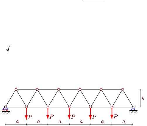
Let us n ow look at a comparis on truss 2 (Fig. 3) with a triangulated lattice. The induction method is obtained for the formula for defle ction
|
|
|
|
1 |
|
m |
|
A a3 |
n2d 3 |
|
|
|
|
|
|
2 (n) |
|
|
Sk sk lk |
P |
n |
|
, |
(7) |
|
|
|
|
EF |
|
8h |
2 EF |
||||||
|
|
|
|
|
|
0 k 1 |
|
|
0 |
|
|
|
|
|
|
m 8n 1, |
|
|
|
||||||
where d |
a2 4 h2 , |
A n2 (10n2 1) / 3 . It is of interest that the recurrence |
||||||||||
|
|
|
|
n |
|
|
|
|
|
|
|
|
equation for the coefficient An coincides with (6) with the only difference of the initial values:
A 3, A |
52, |
A 267,.... The coefficient at d3 |
i easy to de duce and requires no 10 extra |
|
1 |
2 |
|
3 |
|
analytic al calculations of a truss with different numbers of slabs .
Fig. 3. C omparison truss 2; n = 3 |
|
|
|
Let us compare th e dependencies of the deflectio n on the n |
mber of s abs in thre e cases. |
||
Obviously as the l ength of a slab a inc reases, so d oes the deflection. In order to |
ake the |
||
analysi s more analytical, let us consider trusses of |
a constant |
length and thus a L / (2n), |
|
where is the len th of a span of a truss. |
|
|
|
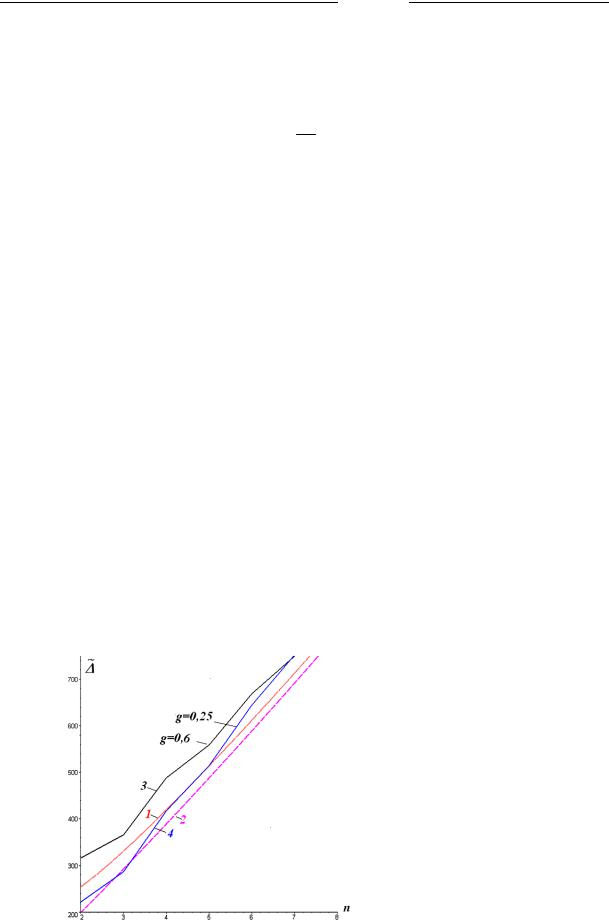
Fig. 4 s hows defl ctions of the truss in question |
see Fig. 1) |
and two comparison |
trusses |
(see Fi g. 2, 3). Th e ratio of he rigidity of belts (for the shared constant total area) can be |
|||
subject to change. Therefore Figure pre ents two curved lines for this tru ss — with a thick-
ened lo wer belt |
(curved lin e |
3, g 0,6 0,5 ) a nd thicken ed upper belt (curved |
line 4, |
g 0,25 0,5 ). |
|
|
|
It is worth noting that for the |
chosen siz es of the t uss these c urved line s intersect at |
n 7. |
|
The deflections of the test trusses (comparison trus ses 1 and 2) are larger or smaller than the deflection of the truss in question depen ding on the number of slabs.
Fractures on the curved line 3 and 4 are due to “flashing” summands in the coefficients (4) includin g the expression like (-1)n. The c rved lines 1 and 2 (al most straig t) always a pproach one another as the number of slabs increases.
89
Scientific Herald of t he Voronezh State University o f Architecture and Civil Engineering. Construction and Architecture
The an alytical for m of prese |
ting the results allows one to obtain a specific ratio of deflec- |
tions accounting fo r the beha |
ior of the curved line s in Graph 4. We have the following limit |
for the comparison truss: |
|
lim 1 1.
n 2
For the truss and c omparison russ 2 in q uestion we have
lim 0 |
|
1 |
. |
|
|||
n 2 |
|
4 p |
|
Let us c ompare th deflection of the truss and comparison truss in question for different reinforcem nt coefficients of the lattice p . According to (3) and (7), we have the ratio 0 2 that can enable us o obtain p * where all the deflections are identical. Let us not fix th e length of the span of the truss as was done in designing the graphs in Fig. 4. He nce an increase in n causes an increase in the span. At g 1/ 2 (the belts have identical section s) we have the correspond ing expres ion (equation root 0 2 ):
p* |
(2n2 n 3 3( 1)n (n 1))h3 (2n2 n 1 ( 1)n (n 1))c3 . |
(8) |
|
2(a3(5( 1) n 3n2 5 4n(3 ( 1)n )) n2d3) |
|
As seen from Fig. 5, this dep endence is strongly sensitive to the height of a truss. For smaller heights the reinforcement coefficient is mo re than 1, for larger ones it is less than 1. The function p*(n) is clearly in homogene us conditioned by the summands in (8) contained in (-1)n. As the deflecti on n increases, the fluctuations of t he graph (particularly for higher trusses) attenuate.
Fig. 4. 1, 2 are comparison trusses 1 and 2, L = 12 m, h = 1 m (see Fig. 2, 3), 3, 4 is a truss (see Fig. 1) at L = 12 m, h = 1 m, p = 1
90