Материал: Scientific Herald of the Voronezh State University of Architecture and Civil Engineering
Issue № 1(29), 2016 |
ISSN 2075-0811 |
Amount of propane prior to another filling of the tank setup, mole |
|
|
|
Relative amount of gas evaporated into the tank setup |
|
|
|
|
|
|
|
Months
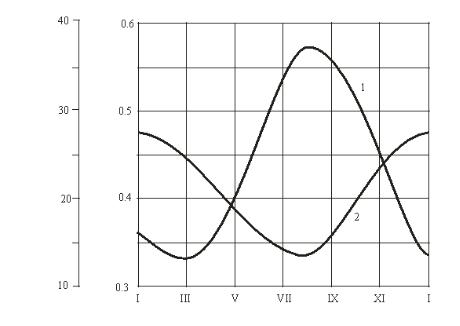
Fig. Calculation characteristics of combined regasification of liquefied gas (the amount of propane in the supplied gas is 50 %):
1 is a relative amount of gas evaporated in the tank setup;
2 is the amount of propane in the tank setup prior to another filling
2. Implementing a mathematical model of a combined regasification of liquefied hydrocarbon gas. For numerical implementation of the suggested mathematical model (1)—(8) the corresponding calculations were performed. The following initial data was used:
––climatic areas of the operation of an underground tank setup –– Orenburg;
––geometric volume of an underground tank setup is 5,0 m3;
––calculation gas pressure in a tank setup Pо = 0,15 МPа (absolute);
––amount of propane in the supplied Ψн = 50 moles %;
––residual gas level in a tank setup σ = 25 %;
––average consumption of liquefied gas per hour g = 10 kg/h.
For a specified consumption of gas in a tank setup, the supply of gas in a tank setup keeps it running for a week. During calculations the annual range of the operation of a setup is broken down into ranges per month where natural temperatures of the base course and the air outside were assumed as specified according to the climate data of the area in [8]. The results are shown in Fig.
As the graph suggests, selection of vapors in an underground tank setup causes significant fluctuations of the composition of the liquefied hydrocarbon gas. The amount of propane in the liquid phase ranged from 50 moles % (following another filling) to 14—28 % (prior to another filling). However due to almost identical physical and chemical properties of propane
11

Scientific Herald of the Voronezh State University of Architecture and Civil Engineering. Construction and Architecture
and butane these fluctuations do not largely impact gas setups. Changes in the Wobbe index describing a heat load of devices is not over ±5 %, which meets the requirements of interchangeability of combustible gases.
Conclusions
1.A mathematical model has been first developed to describe a combined regasification of liquefied hydrocarbon gas and to determine operational parameters of a tank setup in natural and artificial regasification of liquefied gas.
2.The results of numerical implementation of the mathematical model show that the contribution of natural evaporative capacity of a suction tank into the overall performance of a setup changes from 33 in the winter season and to 58 % in the summer season.
3.A combined regasification significantly saves energy for evaporative setups. A switch from artificial to combined regasification of liquefied hydrocarbon gas saves of up to 45—46 % of energy for regasification per year.
References
1.Zimmer LPG Vaporiesd: algas — SDI /1 Form DF-0304. — USA: Seattle, Washington, 2012. — 4 pp.
2.Edvards, R. M. Efficient new heat exchanger suited to LPG vaporization / R. M. Edvards // Oil and Gas Journal. — 2010. — Vol. 65, № 40. — P. 96—98.
3.Kuricyn, B. N. Rezervuarnye sistemy snabzheniya szhizhennym gazom s kombinirovannym otborom zhidkoj i parovoj faz / B. N. Kuricyn, N. N. Osipova, S. S. Kuznecov // Vestnik stroitel'stva i arxitektury. — 2010. — № 1. — S. 352—356.
4.Kuricyn, B. N. E'nergosberegayushhie sistemy rezervuarnogo snabzheniya szhizhennym gazom / B. N. Kuricyn, S. S. Kuznecov // XXV mezhdunar. nauch. konf. «MMTT—25»: sb. nauch. st. — Saratov: SGTU, 2012. — S. 112—115.
5.Nikitin, N. I. Snabzhenie szhizhennym gazom ob'ektov zhilishhno-kommunal'nogo i sel'skogo xozyajstva / N. I. Nikitin. — M.: Strojizdat, 1976. — 105 s.
6.Kuricyn, B. N. Razrabotka matematicheskoj modeli kombinirovannoj regazifikacii szhizhennogo uglevodorodnogo gaza / B. N. Kuricyn, N. N. Osipova, S. S. Kuznecov // Vestnik Sarat. gos. texn. un-ta. — 2011. — Vyp. 1, № 4 (59). — S. 218—224.
7.Kuricyn, B. N. Sistemy snabzheniya szhizhennym gazom / B. N. Kuricyn. — Saratov: Izd-vo SGU, 1988. — 156 s.
8.SP 131.13330.2012. Stroitel'naya klimatologiya. Aktualizirovannaya redakciya SNiP 23-01-99*. — Vved. 2013-01-01. — M.: Minregion Rossii, 2012.
9.Modelirovanie teploobmena pri xranenii szhizhennogo gaza v podzemnyx rezervuarnyx ustanovkax pod vozdejstviem estestvennyx temperatur grunta i naruzhnogo vozduxa / B. N. Kuricyn [i dr.] // Nauchnyj vestnik Voronezhskogo GASU. Stroitel'stvo i arxitektura. — 2012. — № 2 (26). — S. 35—45.
10.Kuricyn, B. N. Optimizaciya regional'nyx sistem snabzheniya szhizhennym uglevodorodnym gazom / B. N. Kuricyn, N. N. Osipova, L. V. Smirnova // Nauchnyj vestnik Voronezhskogo GASU. Stroitel'stvo i arxitektura. — 2009. — № 3 (15). — S. 7—12.
11.Kuricyn, B. N. E'ksperimental'noe issledovanie e'kspluatacionnyx parametrov kombinirovannoj sxemy regazifikacii szhizhennogo uglevodorodnogo gaza / B. N. Kuricyn, N. N. Osipova, S. S. Kuznecov // Nauchnyj vestnik Voronezhskogo GASU. Stroitel'stvo i arxitektura. — 2014. — № 1 (33). — S. 28—33.
12

Issue № 1(29), 2016 |
ISSN 2075-0811 |
BUILDING MATERIALS AND PRODUCTS
UDC 624.016
O. V. Artamonova1, G. S. Slavcheva2
STRUCTURE OF CEMENT SYSTEMS
AS OBJECTS OF NANOMODIFICATION
Voronezh State University of Architecture and Civil Engineering Russia, Voronezh, tel.: (473)271-52-35, е-mail: gslavcheva@yandex.ru 1PhD in Chemistry, Assoc. Prof. of Dept. of Chemistry
2D. Sc. in Engineering, Prof. of Dept. of Building Materials and Construction
Statement of the problem. A key factor in modern concrete technology is integrated modification of their structure, as a rule, based on the sharing of inorganic microand nano-additives and superplasticizers. At the same time structural changes in a cementing substance of concrete, causing a synergistic effect of a fundamental change in their level of quality, remain largely unexplored. For scientific substantiation of processing methods of aimed nanomodification of cement systems the spatial-geometric situation conversion of their structure in the process of hydration and hardening should be considered.
Results. The main periods of heterogeneous processes of structure of cement systems (hardening of the evolutionary route) as the object and purpose of nanotechnology management are analyzed. As a result of the qualitative and quantitative changes in the structure of cement paste at different stages of hydration and hardening presented as an object of nanoimpacts that must be carried out with the terms of the structure of cement stone, meet the criteria for the effectiveness of strength. Legitimate factors of nanomodification of structural elements of cement systems at all stages of the evolutionary route hardening.
Conclusions. Scientific approaches to the modification of nanostructure of cementing material concrete through integrated use of nano-sized additives of optimum size and suitable crystalstructure coupled with superplasticizers are set forth. It is shown that their use makes it possible to regulate the morphology of individual crystals, their shape and dimensions of the agglomerates, the amount of crystals and their contacts to crystalline concretion, to optimize the volume ratio of the cementing material in the morphological differences.
Keywords: solid evolution, cement systems, hydration period, nanomodification.
© Artamonova O. V., Slavcheva G. S., 2016
13

Scientific Herald of the Voronezh State University of Architecture and Civil Engineering. Construction and Architecture
Introduction
In investigating the approaches to nano-modification of the structure of cement concrete we should note that its spatial and geometric and physical and chemical characteristics are the result of macro-modification. It is in this achieved and being achieved by macromethods spatial and geometric setting that processes and phenomena of evolutionary route of the formation of a hardening system “cement-water” are taking place.
In an inhomogeneous composite system of cement as a conglomerate composite are two-three fundamental levels that are part of a cement hydration system (cement binding) that can be considered nano-modification objects. It is these two or three structural level that are the result of the formation and evolution of a cement hydration system.
Evolution of a solid matter in a real cement system is a combination of subsequent and consecutive of physical and chemical phenomena and formation of the solid phase with direct and reverse and cross links. Looking at these phenomena as a general evolutionary route [1], evolution of the solid phase of a matter can be defined as a succession of stages and processes of the emergence, growth and accumulation of a matter, arrangement of a system and composition of original particles by their agglomeration and compaction into aggregates, Ostwald ripening and recrystallization, spontaneous and self-organizing structural formation. It is these stages and phenomena and they must be considered as nanotechnological “objects” in order to perform the modification of synthesized and designed structures of building composites. It is deemed necessary to account for the performance criteria that indicate influences of possible modification on time ( ) and energy in technology (Ент), achieved level of design and (or) functional quality of a material ( R ).
In order to justify possibilities, technological methods and rational boundaries of nanomodification of cement systems, a spatial and geometric setting where an evolutionary route takes place as a hydration process that can be controlled must be investigated.
1. Evolution route and spatial and geometric setting of the transformation of the “ce- ment-water” system as it is going into the solid phase. Evolution route can be related to traditional stages of hydration of a cement system [2—4] in the following way: principal and pre-induction period is when particles of the principal CSH hydrate are generated once clinker touches water; induction period is the growth of the principal hydrate, generation and growth of particles of a secondary CSН hydrate, emergence of ettringite; acceleration process is agglomeration of the principal and secondary CSН hydrates, formation of crystallic joints, mass crystallization of Са (ОН)2; period of slowing down and slow interaction is hydration of
14

Issue № 1(29), 2016 ISSN 2075-0811
C2S, topochemical transformation of agglomerates of the secondary hydrate into a tertiary one, their recrystallization during spontaneous and self-organizing structural formation accompanied by a single three-dimensional structure of a cementation substance.
At each of the stages there is a particular composition and structure of the solid (cement grain), liquid (intergranular volume) phases and pore space all changing at each stage.
In the original system “cement-water” the intergranular volume at the initial stage is 45…60 % of the total volume of the system (Table 1). The distance between cement grains is = 0,956…3,32 mkm, 1—2 units smaller than a cement grain (d = 5…60 mkm) but 1000—10000 times larger than anions and cations [5]:
d(Ca2+) = 1,04 Å = 1,04 10-10 m; d([SiO4]4-) = 2,64 Å = 2,64 10-10 m;
thus the intergranular volume can be considered a homogeneous system. It can be argued that in a spatial and geometric structure of a hydration system there are some processes of the occurrence of a new phase “near the wall” that are caused immediately by the surface of the cement grains. In the intergranular volume a new phase (homogeneous or quasi homogeneous component) is caused by volumes of diffusion near the wall (motions of anions and cations). Therefore evolution route is parallel near the wall and in the intergranular volume.
|
|
|
|
|
|
|
Table 1 |
|
|
Characteristics of the original system “cement-water” when the cement water ratio changes |
|
||||||
|
|
|
|
|
|
|
||
|
Cement |
Water |
Number |
Average dis- |
2+ |
Number of anions |
||
Water/ |
grain |
Number of cations Ca |
[SiO4]4-, |
|||||
volume |
of cement grains |
tance between |
fitting into the |
|||||
cement |
volume |
fitting into the |
||||||
Vw, 3/m3 |
Nc, m3 |
the grains , m |
intergranular space |
|||||
|
Vc, m3/m3 |
intergranular space |
||||||
|
|
|
|
|
||||
0,27 |
0,56 |
0,44 |
1,33 1014 |
0,95 10-6 |
0,92 104 |
0,36 |
104 |
|
|
|
|
|
|
1,24 104 |
|
|
|
0,30 |
0,53 |
0,47 |
1,26 1014 |
1,29 10-6 |
0,49 |
104 |
||
|
|
|
|
|
1,77 104 |
|
|
|
0,35 |
0,49 |
0,51 |
1,17 1014 |
1,84 10-6 |
0,69 |
104 |
||
|
|
|
|
|
2,27 104 |
|
|
|
0,40 |
0,46 |
0,54 |
1,09 1014 |
2,36 10-6 |
0,89 |
104 |
||
|
|
|
|
|
2,74 104 |
|
|
|
0,45 |
0,43 |
0,57 |
1,02 1014 |
2,85 10-6 |
1,08 |
104 |
||
|
|
|
|
|
3,19 104 |
|
|
|
0,50 |
0,40 |
0,60 |
0,96 1014 |
3,32 10-6 |
1,26 |
104 |
||
Possibilities of nano-effects on the system and likely outcomes of changes in the “cement –– water” system are largely determined by sizes and shapes of nanoparticles as it is their geometric parameters (Table 2) that are central to how much they are involved in a new phase
15