Материал: Scientific Herald of the Voronezh State University of Architecture and Civil Engineering

Scientific Herald of the Voronezh State University of Architecture and Civil Engineering. Construction and Architecture
near the wall (an inhomogeneous component) or in the intergranular space (homogeneous or quasi homogeneous component).
|
|
|
|
|
|
|
Table 2 |
|
Number of nano-sized particles of modifiers in the volume of the “cement-water” system |
||||||||
|
|
|
|
|
|
Number of nano- |
|
|
|
|
Dosage |
|
|
|
Number of nano- |
||
Type of the addi- |
|
|
|
|
sized particles in |
sized particles |
||
Water/ |
(mass con- |
Size of particles, |
Volume of |
|||||
tive of nano- |
cement |
centration ), |
m |
3 |
1 m3 of the volume |
fitting into the |
||
sized particles |
1 particle, m |
of the cement + |
intergranular |
|||||
|
% |
|
|
|
||||
|
|
|
|
|
+ water system |
space |
||
|
|
|
|
|
|
|||
|
|
|
|
|
12,48 1020 |
|
||
SiO2 nH2O |
|
|
= 10 10 9 |
5,23 10 25 |
100 |
|||
Ball like par- |
0,27 |
0,01 |
|
|
|
|
|
|
= 50 |
10 9 |
6,54 10 23 |
9,98 1018 |
10 |
||||
ticles |
|
|
||||||
|
|
|
|
|
|
|
||
|
|
|
|
|
|
|
|
|
Nano tubes of |
|
|
= 25 10 9 |
|
|
|
||
chrysotile |
0,33 |
0,01 |
4,90 10-23 |
1,47 1018 |
Length 18 |
|||
l = 100 |
10 9 |
|||||||
[Mg3Si2O5(OH)4] |
|
|
|
|
|
|||
|
|
|
|
|
|
|
||
Carbon fulleroid |
0,33 |
0,01 |
= 2 |
10 9 |
6,28 10-25 |
1,2 1020 |
Length 10 |
|
nano tubes |
l = 200 |
10 9 |
||||||
|
|
|
|
|
||||
Nano tubes |
0,33 |
0,01 |
= 80 |
10 9 |
7,536 10-22 |
9,1 1016 |
Length 12 |
|
Astralen C |
l = 150 |
10 9 |
||||||
|
|
|
|
|
||||
|
|
|
|
|
|
|
|
|
The “cement-water” system undergoes qualitative and quantitative changes along the evolution route of hardening. Quantitative changes are due to new formations of a cementation substance, new pore space and decrease in the original volume of the phase forming component (cement grains) and liquid phase. Excessive phase forming component in the original system is necessary for the structure of a solid matter to form. As the structure further takes shape, coagulation and condensation crystallization contacts are due to physical and chemical link of a tempering fluid. It is a new phase of a larger volume and specific surface than the original solid phase makes it possible for a plastic disperse system to transform into a solid structure.
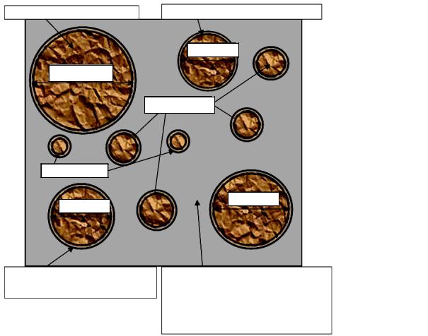
Qualitative transformations into the original period (0…5 sec) (Fig. 1) correspond with the stage of the emergence of a new phase in the general evolution route and are caused by the formation of a film of principal hydrates on cement grains and structuring of the liquid phase. The liquid phase in the system is divided into absorption (film) and free with different chemical potentials. Absorption water generates a film 3…10 nm on cement grains, capillary and free water in the intergranular space form a solution with ions
OH– , Ca2 , CaOH , HSiO3 , SiO32 , H2SiO24 , Al3 ,AlO2 .
16
Issue № 1(29), 2016 |
ISSN 2075-0811 |
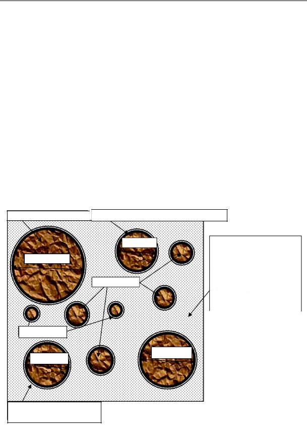
During the pre-induction period (5 seс…30 min, stage of the emergence of a new phase) (Fig. 2) in the liquid phase the structure (deformation) of the structure of principal hydrates is transformed into secondary hydrates accompanied by a free lime.
Grains of cement |
|
Film of the principal hydrate ≈ 0,8 nm, C/S ≈ 3 |
d ≈ 15 mkm
d > 60 mkm
d ≈ 5 + 10 mkm
d < 5 mkm
d ≈ 20 mkm
d ≈ 30 mkm
|
Absorption water |
|
|
|
Intergranular volume filled with capillary |
|
||||
|
(films nm ≈ 3––10 nm) |
|
|
|
and free waterи(solution, |
with, Ca |
, SiO |
, |
|
|
|
|
|
|
|
|
|||||
|
|
|
|
|
|
|||||
|
|
|
|
|
HSiO |
OH AlO H SiO |
|
|
||
|
|
|||||||||
|
Fig. 1. “Cement-water” |
|
|
|||||||
|
system at the initial stage of hydration, = 0…5 sec |
|||||||||
On the surface of a cement |
grain there is |
a film CSH (I) |
of |
the secondary hydrate |
||||||
( 6 nm, C/S 2). Gypsum is dissolved and enters into a reaction near the parts of the surface of cement grains where the phases C3A and C4AF dominate; a jelly-like product near these phases is rich in aluminium, calcium and sulphate ions respectively. There are rod crystals of AFt-phase emerging in the gel and solution. In the liquid phase of the intergranular volume there is a disperse system, i.e. sol with emerging crystals of a new phase. Subsequently the basic capacity decreases. As principal hydrates are forming, they dissociate into calcium to transform into a solution. It is saturated with calcium ions in Са(ОН)2 very promptly but the concentration keeps rising more making the solution oversaturated. This is known to cause the induction period to occur with clinker phases dissolving extremely slowly.
17
Scientific Herald of the Voronezh State University of Architecture and Civil Engineering. Construction and Architecture
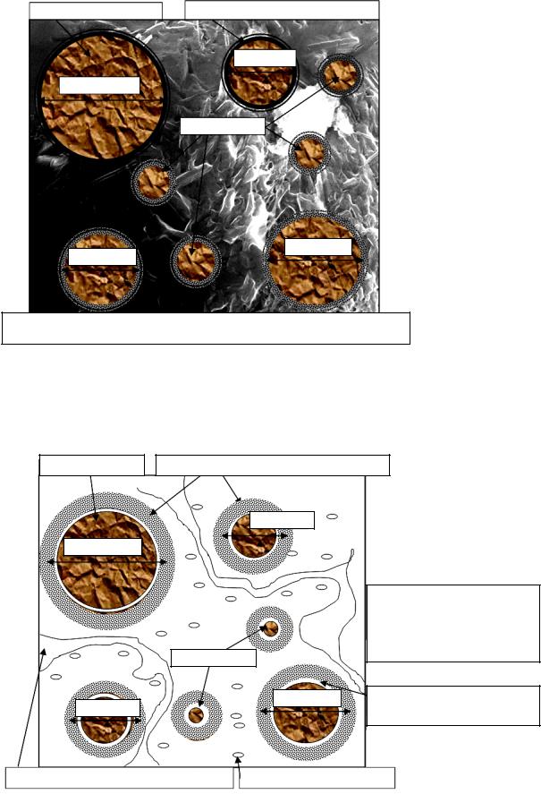
During the induction period primarily associated with the growth of particles in the general evolution route, the Ca/Si ratio in the solution keeps increasing and decreases in the liquid phase. As the basic capacity of the hydrosilicate gel drops, its structure changes and the porosity increases. The induction period is over as soon as the gel is resistant enough to prevent the free ion exchange between the solid and liquid phases. Throughout the induction period the original disperse system “water –– cement” transforms into the structure of a solid body, i.e. the cement stone (Fig. 3). The solid phase of the cement stone is on the surface of cement grains in the form of a secondary hydrate film ( 100 nm, C/S 2) with a low specific surface; in the intergranular gaps there are high dispersion Са(ОH)2, some distance away from the cement grains there are short, blunt sticks (l 250 nm, 100 nm) are calcium hydrosulphoaluminates (C6AH10, C3AH6). The liquid phase is free water with an average chemical potential capillarly connected with a low chemical potential, absorption structured water.
Grains of cement
d > 60 mkm
d < 5 mkm

 Film of the principal hydrate ( ≈ 6 nm, C/S ≈ 2)
|
|
|
|
In the intergranular volume there |
||||||
|
d ≈15 mkm |
|||||||||
|
|
|
|
is capillary and free water |
CaOH |
|||||
|
|
|
|
|||||||
|
|
|
|
high alumina gel, |
|
|
||||
|
|
|
|
|
|
|
ettringite |
|
||
|
|
|
|
(solution with |
,Ca , |
|
||||
d ≈ 5 + 10 mkm |
|
|
germs, |
и |
|
|
, |
|||
|
|
|
|
SiO HSiO |
|
OH) |
AlO |
|
||
|
|
|
|
|
||||||
|
|
|
|
H SiO |
|
|
|
|
|
|
d ≈ 30 mkm
d ≈ 20 mkm
Absorption water (films ≈ 3––10 nm)
Fig. 2. “Water –– cement” system in the pre-induction period of hydration, = 5 с…30 min
18
Issue № 1(29), 2016 |
|
|
|
|
|
|
ISSN 2075-0811 |
|||
|
|
|
|
|
|
|
|
|
|
|
|
|
|
|
|
|
Film of the principal hydrate ( ≈ 100 nm, C/S ≈ 2) |
|
|||
|
|
Grains of cement |
||||||||
|
|
|
|
|
|
|
|
|
|
|
|
|
|
|
|
|
|
d ≈15 mkm |
|
|
|
|
|
|
|
|
|
|
|
|
|
|
|
|
d > 60 mkm |
|
|
|
|
|
|
|
|
|
|
|
|
|
|
|
|
|||
|
|
|
|
|
|
d ≈ 5 + 10 mkm |
|
|
|
|
d ≈ 30 mkm
d ≈ 20 mkm
In the intergranular volume there is capillary and free water, ettringite crystals l ≈ 150––250 nm, Ca OH d ≈ 50––100 nm
Fig. 3. Cement stone in the induction period of hydration, = 30 min…2 h
Accelaration is mainly associated with the agglomeration stage (Fig. 4) of principal and secondary hydrates and crystal joints.
Grains of cement
d > 60 mkm
d ≈ 20 mkm
Gel envelope ( ≈ 0,5–––1 nm, C/S ≈ 1,6)
d ≈15 mkm
d ≈10 mkm
d ≈ 30 mkm
Newly formed substances in the volume: gel CSH (C/S ≈ 2), ettringite crystals l ≈ 1––2 nm,
Ca OH d ≈ 100––500 nm
Gap ( ≈ 1mkm) between a cement grain and gel envelope CSH
Capillary pores d = 10––100 nm |
|
Nanopores d = 3––10 nm |
|
|
|
Fig. 4. Cement stone during the acceleration of hydration, = 2…12 h
19

Scientific Herald of the Voronezh State University of Architecture and Civil Engineering. Construction and Architecture
The dissolution of the original phases and precipitation of the product of the oversaturated solution dominates hydration; such a “cross solution” mechanism is in place till a product layer is thick enough and resistant for free ion exchange to occur. At this point fine cement grains dissolve completely and redeposit into hydration products around larger particles. A layer of hydrosilicate gel becomes thicker on the outside absorbing rod crystals of ettringite. The surface of cement grains is completely covered with amorphous and (dentrite like) morphological CSH glue in the form of fibers radially going through cement grains or in the form of foil formations with a developed specific surface ( 0,5…1 mkm, C/S 1,6); clusters of Са(ОН)2 strips = 10 nm are poured into CSH gel. Envelopes of the hydrates remain permeable through the entire period. As a reaction at this point is due to the solution and precipitation, there is a space filled with liquid between the envelopes of products and a grain that was not involved in the reaction. As the original grain dissolves, this space increases and once the hydration is at its peak, the thickness of the gap is about0,5…1 mkm. As a result of mass crystallization Са(ОН)2, in the intergranular volume there is a spatial carcass of portlandite. There is a structure of the porous space presented by capillars d 100 nm, 10…100 nm and nanopores d = 3…10 nm. By the time the thickness of the product layers is about 0,5…1 mkm, the envelopes of adjoining grains merge, which is the end of setting (8…12 h). After that the growth of the surface of the reaction is over and followed by slowing down.
In the period of slowing down self-organizing structural forming dominates. As envelopes of hydrates are more resistant, there are newly formed substances emerging on the inside. Spaces between the envelopes and grains that were not involved in the reaction are filled with the product. After 7 days gaps between the grains that were not involved into the reaction and envelopes of products are gone and about 30% of the cement takes part in the reaction at this point. The envelopes are about 8 mkm thick and are mainly made up of the material deposited on the inside (Fig. 5). In the intergranular volume there is “an outside product” of hydration due to the interaction between CSH and Са(ОH)2 with an envelope of jelly-like particles CSH(II), ettringite crystals and AFt-phases l 2…10 mkm, hexagonal plates of Са(ОH)2 d = 10…100 mkm. The structure of the porous space is presented with capillars d = 10…100 mkm, 100…1000 nm and nanopores d = 10…20 nm.
20