Материал: m013202e
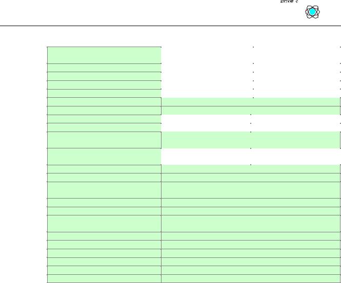
TECHNICAL DATA:
Number of function modules
Digital peripheral signals
Analog peripheral signals
Configuration possibility
Bus connection
Voltage supply
Input current
Internal current
Power jumper contacts
Maximum current supplied to K-Bus for internal module use
Voltage power jumper contacts
Current power jumper contacts
Data contacts
Voltage drop via data contacts
Housing material
Marking
Wire connection
Mounting position
Type of protection
Isolation
Operating temperature
Dimensions (mm) W x H x L
INTEBUS S / Enclosure and specifications
|
|
|
|
|
|
|
|
|
|
|
|
|
|
|
|
|
|
|
|
|
|
|
|
750-304 |
750-324 |
|
|||
dig.+analog |
digital |
||||
64 |
32 |
|
|
||
256 |
64 |
|
|
||
32 |
--- |
|
|
||
via PC or control |
--- |
|
|
||
2 D-SUB with protection against vibration
24V DC (-15%/+20%)
105 mA typ; 900 mA max. |
85 mA typ.; 500 mA max. |
400 mA |
400 mA |
blade / spring contact slide contact, self-cleaning
1.75 A |
on request |
|
|
24 V DC
10A DC
slide contacts, 1.5 u hard gold-plated self-cleaning
<1V with 64 wired special function modules
Polycarbonat, Polyamid 6.6
standard markers WAGO BR247/248 marker cards 8 x 47mm
CAGE CLAMP; 0.08mm2 -2.5mm2 /AWG 28 -14
any position
IP 20
500 V system / power supply
0°C...+55°C
51 x 65* x 100 (*from upper edge of the carrier rail)
9
:$*2Ç, 2Ç6<67(0
Interbus S buscoupler with extended diagnostics 750-304/000-001
The Interbus S buscoupler with no. 750-304/000-001 has the possibility of extented diagnostic functions. The technical data is the same as 750-304.
Different from the standard buscoupler, a word for diagnostic messages is put into the input data process image and a word for the control of the diagnostic input is put into the output data process image.
The maximum number of input and output modules is reduced by the additional diagnostic function because Interbus S transmits only 31 words of a process image.
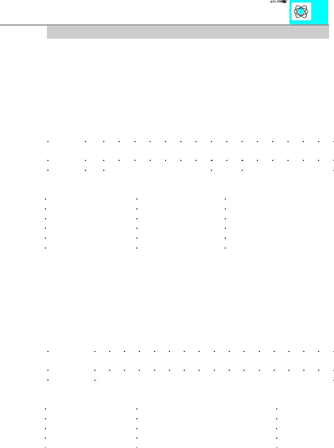
Order of the diagnostic status word: |
|
|
|
|
|
|
|
|
|
|||||||
|
|
|
|
|
|
|
|
|
|
|
|
|
|
|
|
|
Bit of the |
15 |
14 |
13 |
12 |
11 |
10 |
9 |
|
7 |
6 |
5 |
4 |
3 |
2 |
1 |
0 |
status word |
|
|
|
|
|
|
|
|
|
|
|
|
|
|
|
|
|
error |
error code (s. table) |
|
Channel |
Module |
|||||||||||
The error code is shown in the following table:
Error code |
Description |
0 |
unknown fault |
5 |
defective fuse |
10 |
broken wire |
15 |
short circuit |
Channel: This is the location for the fault input of a module. The counting is done in the same way as numbering channels.
Module: This is the number of the module. Counting starts at the fieldbus coupler. The first module attached to the coupler is module 0.
The diagnostic control word is for diagnostic actions. E.g. error messages can be cleared in this way.
Order of the diagnostic control word:
|
Bit of the |
15 |
14 |
13 |
|
12 |
11 |
10 |
9 |
8 |
7 |
6 |
5 |
4 |
3 |
2 |
1 |
0 |
||
|
control word |
|
|
|
|
|
|
|
|
|
|
|
|
|
|
|
|
|
|
|
|
|
|
Actions |
|||||||||||||||||
|
The actions are coded as follows: |
|||||||||||||||||||
|
|
|
|
|
|
|
||||||||||||||
|
Actions |
|
|
|
Description |
|
||||||||||||||
|
0x00 |
(0) |
|
|
|
no action |
|
|||||||||||||
|
0x01 |
(1) |
|
|
|
Acknowledge diagnostic control word |
|
|||||||||||||
|
0x80 |
(128) |
|
|
|
Clears all error messages in the buffer |
|
|||||||||||||
INTEBUS S / Enclosure and specifications |
10 |
:$*2Ç, 2Ç6<67(0

4 INTERBUS S
The Interbus S system (DIN 19245 part 1.2) is set up as a data ring with a central master slave access procedure. All modules are understood as one logical module. Each partner receives data at its input and sends it to the next partner at its output. There is no addressing with a data frame because each partner knows by special control signals (CLOCK, RESET, SELECT, CONTROL) where it is placed in the ring. So there is no bus address. „Addressing“ is done via the physical place in the system.
Interbus S has the structure of a spatially distributed shift register. Each cycle is input and output at the same time. While the master gives output data to the shift register, it gets input data from the other end of the ring.
Each part of Interbus S has an ID register. This register keeps information about the type of module, the number of I/O registers and the status and error information.
Interbus S has two general operating modes:
1) ID cycle
The interface module of all devices connected to the bus system reads out the ID register in the ID cycle and builds up the process image with the aid of this information. The cycle serves as an initialization and is carried out on request.
2) Data cycle
Within the data cycle all input data from the registers is transferred from all devices into the master card (Host Controller) and all output data from the master card (Host controller) to the devices.
4.1 Master Cards (Scanners, Host Controllers)
The operation of the master is carried out in most cases via a central controller like a PLC, PC or NC. Connection to the remote stations is made via master cards.
Common master modules are:
-Phoenix IBS S5 DCB/I-T
-Phoenix IBS S5 DSC/I-T
-Phoenix 100 CB-T
-Hilscher CIF 30 (via Synergetic Micro Systems in USA)
INTERBUS S / Interbus S |
11 |
:$*2Ç, 2Ç6<67(0

4.2 Configuration software
In order to make the connection between a PLC or PC and the remote stations, the master cards must be configured with the individual station data.
For this, the following software packages are available. For example, the following are available from Phoenix:
-IBS SYS SWT
-IBS CMD SWT
INTERBUS S / Interbus S |
12 |
:$*2Ç, 2Ç6<67(0
5 Configuration of the fieldbus node in the master
5.1 Identification Code
In the ID cycle which is carried out for the initialization of the Interbus system, the users connected users are identified by their function and their byte length. The Interbus S coupler identifies its length after being started in the initialization phase of the bus modules and forms a corresponding ID code. To this effect each slave has an implemented identification register (ID register) comprising 2 bytes.
A 2 byte wide data unit is called a word. It enables the encoding of 65536 different states. In Interbus S, different types of users and data widths are called for the coding. This enables the master to find out what type the device belongs to, which means for
example, recognizing either frequency inverters or I/O units, like the :$*2Ç, 2Ç6<67(0 In Interbus S the manufacturers of device types are not
recognized. The structure of the ID code is explained below as well as the significance of the individual bits of the ID code.
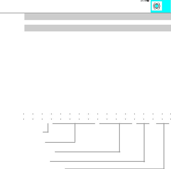
The length information can be coded from 0 to 32 words:
15 |
14 |
13 |
12 |
11 |
10 |
9 |
8 |
7 |
6 |
5 |
4 |
3 |
2 |
1 |
0 |
|
|
|
|
|
|
|
|
|
|
|
|
|
|
|
|
|
|
messages
data width
class of user
type of user
data direction I, O, I/O
Table 2: Structure of the Interbus ID code
-In the ID registers, the device group is coded in the lowest value (LSB) 8 bits (ID 0 to 7).
-In the following 5 bits (ID 8 to 12), the data width is coded. The 3 bits with the highest value (MSB) (ID 13 to 15) are used for management functions. Via these bits, dynamic fault messages are transferred during operation. These bits are not defined by the hardware.
INTERBUS S / Configuration |
13 |
:$*2Ç, 2Ç6<67(0