Материал: m013202e
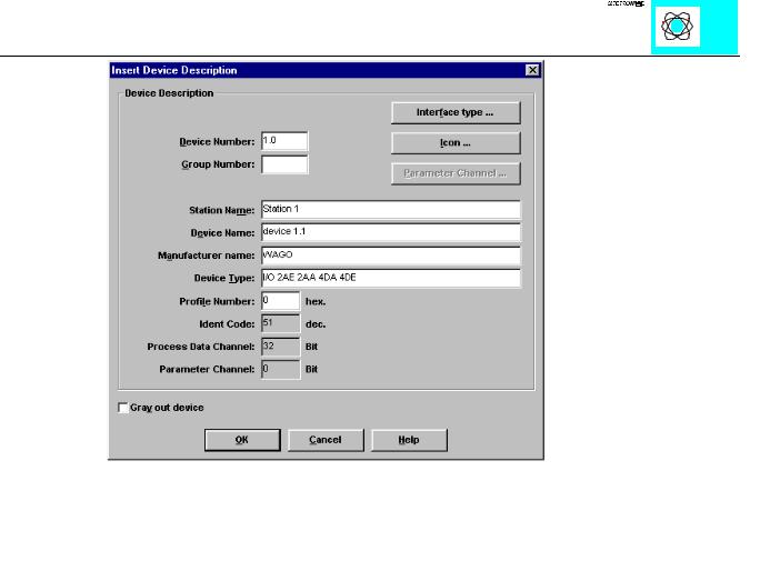
Ill. 14: Description of user
INTERBUS S / Configuration |
19 |
:$*2Ç, 2Ç6<67(0
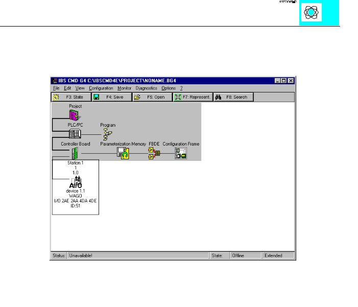
After all data has been entered and stored via OK, the station created with the WAGO Interbus coupler is then integrated into the fieldbus system being set up.
This station is displayed via the bus structure that has now been integrated:
INTERBUS S / Configuration |
20 |
:$*2Ç, 2Ç6<67(0
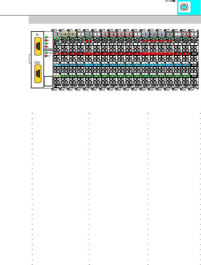
5.4 Example of an application
Ill. 19: Example of an application
The Interbus S station is composed as follows:
Function module |
Process image inputs |
Process image outputs |
1; Digital input |
PI 32.0 |
|
1; Digital Input |
PI 32.1 |
|
2; Digital Input |
PI 32.2 |
|
2; Digital Input |
PI 32.3 |
|
3; Voltage supply |
------ |
------ |
4; Analog Input |
PI 20 |
|
4; Analog Input |
PI 22 |
|
5; Voltage supply |
------ |
------ |
6; Digital Output |
|
PI28.0 |
6; Digital Output |
|
PI28.1 |
7; Digital Output |
|
PI28.2 |
7; Digital Output |
|
PI28.3 |
8; Digital Output |
|
PI28.4 |
8; Digital Output |
|
PI28.5 |
9; Digital Output |
|
PI28.6 |
9; Digital Output |
|
PI28.7 |
10; Voltage supply |
------ |
------ |
11; Analog Output |
|
PI 20 |
11; Analog Output |
|
PI 22 |
12; Analog Input |
PI 24 |
|
12; Analog Input |
PI 26 |
|
13; Analog Output |
|
PI 24 |
13; Analog Output |
|
PI 26 |
14; Analog Input |
PI 28 |
|
14; Analog Input |
PI 30 |
|
15; Voltage supply |
------ |
------ |
16; Digital Output |
|
PI29.0 |
16; Digital Output |
|
PI29.1 |
17; End module |
------ |
------ |
Table 5: Assignment of the process image
INTERBUS S / Configuration |
21 |
:$*2Ç, 2Ç6<67(0
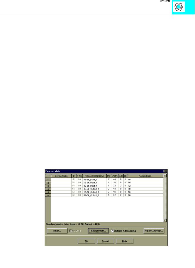
The addresses indicated in the table results from the master configuration started in the basic address. By the internal structure of the Interbus coupler, the process image is divided as follows:
|
O0 |
|
Output data |
.... |
|
|
.....word orientated data |
|
|
.... |
|
|
Ox |
|
|
Ox+1 |
bit orientated data |
|
Ox+y |
|
|
|
|
|
|
|
|
I0 |
|
Input data |
.... |
|
|
....word orientated data |
|
|
.... |
|
|
Ix |
|
|
Ix+1 |
bit orientated data |
|
Ix+y |
|
|
|
|
Due to this division, the first addresses allocated in the configuration are reserved for the analog inputs and outputs. The counting direction is from left to right and starts with the first analog channel next to the bus coupler.
Ill. 21: Definition inputs/outputs
INTERBUS S / Configuration |
22 |
:$*2Ç, 2Ç6<67(0
6 Buscoupler startup and troubleshooting
After configuration of the master connection and electrical installation of the fieldbus node/station, operation of the system can begin.
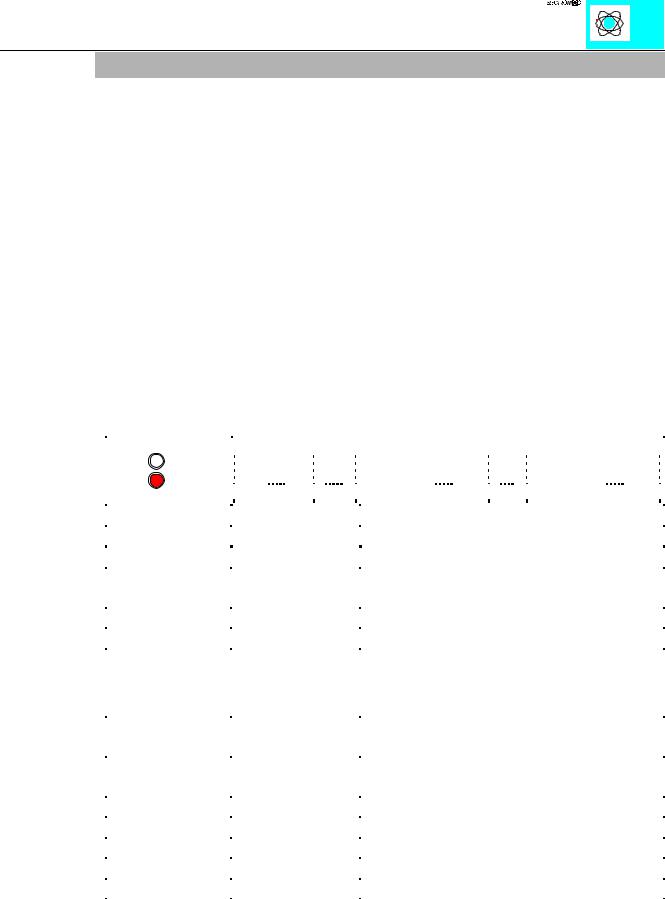
After power to the Buscoupler and I/O modules has been applied, the Buscoupler verifies all internal functions, components and the communication interface by an internal diagnostic routine. Then the function modules and the existing configuration is determined. At the same time a hidden file is stored. It consists of an input and an output area which is located on the fieldbus RAM of the log chip. During the power up phase the ‘I/O ERR’ LED flashes with an increased frequency. After a faultless power up the fieldbus coupler enters the state ‘fieldbus start’. The green LED ‘RUN’ indicates that the Bus is operating normally.
In case of a fault the red ‘I/O ERR’ LED will continue flashing.
By counting the number and frequency of flashes the fault can be easily identified quickly and accurately. A varying number of flashes and frequencies defines the fault. The table below describes the fault condition based on the counted number of ‘I/O ERR’ LED flashes.
, 2 581 |
|
|
|
|
|
|
|
|
|
|
|
|
|
|
|
|
|
|
|
|
|
|
|
|
|
|
|
|
|
|
|
|
|
|
|
|
|
|
|
|
|
|
|
|
|
|
|
|
|
|
|
|
|
|
|
|
|
|
|
|
|
|
|
|
|
|
|
|
|
|
|
|
|
|
|
|
|
|
|
|
|
|
|
|
|
|
|
|
|
|
|
|
|
|
|
|
|
|
|
|
|
|
|
|
|
|
|
|
|
|
|
|
|
|
|
|
|
|
|
|
|
|
|
|
|
|
|
|
|
|
|
|
|
|
|
|
|
|
|
|
|
|
|
|
|
|
|
|
|
|
|
|
|
|
|
|
|
|
|
|
|
|
|
|
|
|
|
|
|
|
|
|
|
|
|
|
|
|
|
|
|
|
|
|
|
|
|
|
|
|
|
|
|
|
|
|
|
|
|
|
|
|
|
|
|
|
|
|
|
|
|
|
|
|
|
|
|
|
|
|
|
|
|
|
|
|
|
|
|
|
|
|
|
|
|
|
|
|
|
|
|
|
|
|
|
|
|
|
|
|
|
|
|
|
|
|
|
|
|
|
|
|
|
|
|
|
|
|
|
|
|
|
|
|
|
|
|
|
|
|
|
|
|
|
|
|
|
, 2 (55 |
|
|
|
|
|
|
|
|
|
|
|
|
|
|
|
|
|
|
|
|
|
|
|
|
|
|
|
|
|
|
|
|
|
|
|
|
|
|
|
|
|
|
|
|
|
|
|
|
|
|
|
|
|
|
|
|
|
|
|
|
|
|
|
|
|
|
|
|
|
|
|
|
|
|
|
|
|
|
|
|
|
|
|
|
|
|
|
|
|
|
|
|
|
|
|
|
|
|
|
|
|
|
|
|
|
|
|
|
|
|
|
|
|
|
|
|
|
|
|
|
|
|
|
|
|
|
|
|
|
|
|
|
|
|
|
|
|
|
|
|
|
|
|
|
|
|
|
|
|
|
|
|
|
|
|
|
|
|
|
|
|
|
|
|
|
|
|
|
|
|
|
|
|
|
|
|
|
|
|
|
|
|
|
|
|
|
|
|
|
|
|
|
|
|
|
|
VHTXHQFH |
|
|
3DXVH |
|
|
|
|
VHTXHQFH |
|
|
3DXVH |
|
VHTXHQFH |
|
|
|
||||||||||||||||||||||||||
|
|
|
|
|
|
|
|
|
|
|
|
|
|
|
|
|
|
||||||||||||||||||||||||||||||
|
|
|
|
|
|
|
|
|
|
|
|
|
|
|
|||||||||||||||||||||||||||||||||
|
|
|
|
|
|
|
|
|
|
|
|
|
|
|
|
||||||||||||||||||||||||||||||||
|
|
|
|
|
|
|
|
|
|
|
|
|
|
|
|
||||||||||||||||||||||||||||||||
2. Blinking sequence |
|
|
|
|
3. Blinking sequence |
description |
|
|
|
|
|
|
|
|
|
|
|
|
|
|
|
|
|
|
|
||||||||||||||||||||||
error code |
|
|
|
|
|
|
|
error argument |
|
|
|
|
|
|
|
|
|
|
|
|
|
|
|
|
|
|
|
|
|
|
|
||||||||||||||||
1 |
0 |
|
|
|
|
|
|
|
|
|
|
|
|
|
|
|
|
|
|
|
|
|
|
|
|
|
|
|
|
|
|
|
|
|
|
|
|||||||||||
|
1 |
|
|
|
|
|
|
|
|
|
|
|
|
overflow of internal buffer for inline code |
|
|
|
|
|
|
|||||||||||||||||||||||||||
|
|
|
|
|
|
|
|
|
|
|
|
|
|
|
|
|
|
|
|
|
|
|
|
|
|
|
|
|
|
|
|
|
|
|
|
|
|
|
|
|
|
|
|
|
|
|
|
|
2 |
|
|
|
|
|
|
|
|
|
|
|
|
unknown data type |
|
|
|
|
|
|
|
|
|
|
|
|
|
||||||||||||||||||||
2 |
0 |
|
|
|
|
|
|
|
|
|
|
|
|
error in programmed process image |
|
|
|
|
|
|
|
|
|
||||||||||||||||||||||||
|
|
|
|
|
|
|
|
|
|
N (N>0) |
|
|
|
|
|
|
error |
|
in |
|
comparison |
of |
tables: |
module |
N |
|
|||||||||||||||||||||
|
|
|
|
|
|
|
|
|
|
|
|
|
|
|
|
|
|
|
|
|
|
|
|
|
(programmed configuration), passive modules like supply |
|
|||||||||||||||||||||
|
|
|
|
|
|
|
|
|
|
|
|
|
|
|
|
|
|
|
|
|
|
|
|
|
terminal blocks do not count |
|
|
|
|
|
|
|
|
|
|
|
|||||||||||
|
|
|
|
|
|
|
|
|
|
|
|
|
|
|
|
|
|
|
|
|
|
|
|
|
|
|
|
|
|
|
|
|
|
|
|
|
|
|
|
|
|
|
|
|
|||
3 |
0 |
|
|
|
|
|
|
|
|
|
|
|
|
modules have identified error in fieldbus commands |
|
|
|
||||||||||||||||||||||||||||||
|
|
|
|
|
|
|
|
|
|
|
|
|
|
|
|
|
|
|
|
|
|
|
|
|
|
|
|
|
|
|
|
|
|
|
|
|
|
|
|
|
|
|
|
|
|||
4 |
0 |
|
|
|
|
|
|
|
|
|
|
|
|
data error on fieldbus or fieldbus break at the coupler |
|
|
|
||||||||||||||||||||||||||||||
|
|
|
|
|
|
|
|
|
|
|
|
|
|
|
|
|
|
|
|
|
|
|
|
|
|
|
|
|
|
|
|
|
|
|
|
|
|
|
|
|
|
|
|
|
|
||
4 |
|
|
|
|
|
|
|
|
|
N (N>0) |
|
|
|
|
|
|
fieldbus break after module N |
|
|
|
|
|
|
|
|
|
|
|
|||||||||||||||||||
5 |
|
|
|
|
|
|
|
|
|
|
N |
|
|
|
|
|
|
filedbus error in register communications with module N |
|
|
|
||||||||||||||||||||||||||
6 |
|
|
|
|
|
|
|
|
|
|
|
|
|
|
|
|
|
|
|
|
|
|
|
|
error in INTERBUS-S configuration telegram |
|
|
|
|
|
|
||||||||||||||||
|
0 |
|
|
|
|
|
|
|
|
|
|
|
|
too lillte configuration data |
|
|
|
|
|
|
|
|
|
|
|
|
|
||||||||||||||||||||
|
|
|
|
|
|
|
|
|
|
N (0<N<65) |
error in 1st configuration byte |
|
|
|
|
|
|
|
|
|
|
|
|||||||||||||||||||||||||
Table 5: Diagnosis LEDs - on buscoupler
INTERBUS S / Startup |
23 |
:$*2Ç, 2Ç6<67(0