Материал: m013802e_a

Access word for word to the digital input and output modules is made in accordance with the following table:
Digital inputs/ |
8. |
7. |
6. |
5. |
|
4. |
3. |
2. |
1. |
16. |
15. |
14. |
13. |
|
12. |
11. |
10. |
9. |
outputs |
|
|
|
|
|
|
|
|
|
|
|
|
|
|
|
|
|
|
|
|
|
|
|
|
|
|
|
|
|
|
|
|
|
|
|
|
|
Process data word |
Bit |
Bit |
Bit |
Bit |
|
Bit |
Bit |
Bit |
Bit |
Bit |
Bit |
Bit |
Bit |
|
Bit |
Bit |
Bit |
Bit |
|
15 |
14 |
13 |
12 |
|
11 |
10 |
9 |
8 |
7 |
6 |
5 |
4 |
|
3 |
2 |
1 |
0 |
|
|
|
|
|
|
|
|
|
|
|
|
|
|
|
|
|
||
Byte |
|
|
|
High-Byte |
|
|
|
|
|
|
Low-Byte |
|
|
|
||||
|
|
|
|
|
D1 |
|
|
|
|
|
|
|
D0 |
|
|
|
||
Table 5.10: Allocation of digital inputs/outputs for process data word, coupler |
|
|
|
|
|
|
|
|
||||||||||
5.1.3 Addressing the I/O modules
∙The arrangement of the I/O modules in a node is optional.
∙The I/O module addressing is based on the attendant coupler.
∙Addressing is organised word for word and starts with the word address ‘0’ both for the inputs as well as the outputs.
∙The I/O module addressing corresponds to the sequence of their arrangement behind the coupler. Addressing starts with the bus coupler, which can assign one or more words per channel. This is followed by the I/O module addresses which can assign one or two bits per channel. For the number of input and output bits or bytes please refer to the corresponding I/O module data sheets.
∙Addressing of I/O modules which are assigned to one or two bits per channel is also made word for word. In other words in each case 16 inputs or outputs are allocated one word. If less channels are present the remaining bits of the word remain free or are reserved for extensions.
∙If a node is extended by additional I/O modules for which one or more words are assigned per channel, the I/O module addresses are displaced by one or two bits per channel.
Data width ÿ 1 Word / channel |
Data width = 1 Bit / channel |
Analog input modules |
Digital input modules |
Analog output modules |
Digital output modules |
Input modules for thermal elements |
Digital output modules with diagnosis (2 Bit / channel) |
Input modules for resistance sensors |
Power supply modules with fuse holder / diagnosis |
Pulse width output modules |
Solid State power relay |
Interface module |
Relay output modules |
Up/down counter |
|
I/O modules for angle and path measurement |
|
Table 5.11: I/O module data width |
|
32 |
MODBUS / Configuration |
15.12.99
5.1.4 Application examples
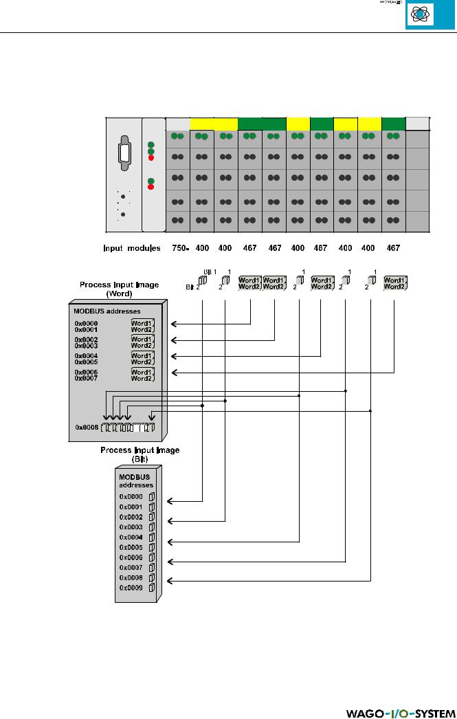
The following figure is an example for a process input image. The configuration comprises of 10 digital and 8 analog inputs. The process image thus has a data length of 8 words for the analog and 1 word for the digital inputs, i.e. 9 words.
Fig. 5.3: Example for process input image, coupler
MODBUS / Configuration |
33 |
15.12.99
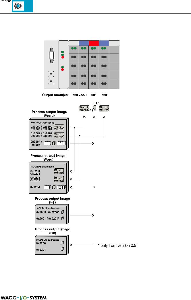
The following configuration comprises of 2 digital and 4 analog outputs. This is an example for a process output image. It comprises of 4 words for the analog and one word for the digital outputs.
Fig. 5.4: Example for process output image, coupler
34 |
MODBUS / Configuration |
15.12.99