Материал: m013802e_a

|
|
|
|
|
|
|
|
|
|
|
|
|
|
|
|
|
|
|
|
|
|
|
|
22 |
MODBUS / Technische Daten |
||
15.12.99
4 MODBUS
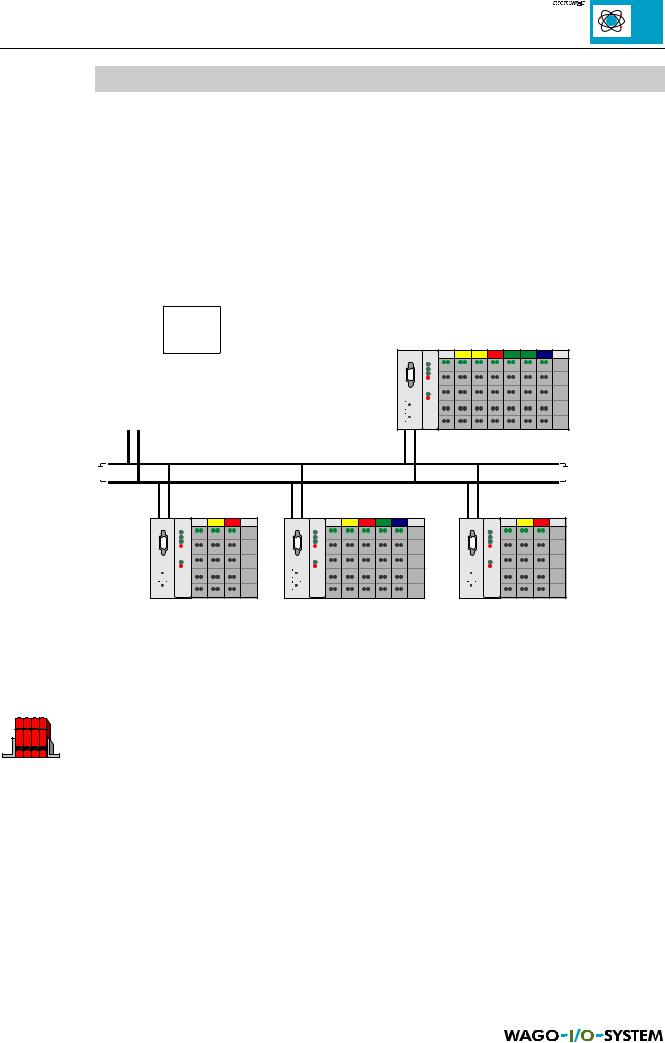
MODBUS is a master/slave system. The master is a superimposed control unit, e.g. a PC or a PLC device. The MODBUS coupler/controller of the WAGO-I/O-SYSTEMS are slave devices.
Bus conflicts do not occur because only one node is sending. The master makes a query for communication. This query can be sent to a specific node or to all nodes as a broadcast message. The nodes receive the query and return a response to the master, depending on the kind of query.
Fig. 4.1: Example of a MODBUS topology
This bus topology is only valid for the variants with the RS 485 interface. With RS 232 it is only possible to have a peer-to-peer connection.
You will find further information on MODBUS in:
Online information on MODBUS: http://www.modicon.com/techpubs/toc7.html
MODBUS tools for PC: |
http://www.win-tech.com |
MODBUS / Description MODBUS |
23 |
15.12.99

|
|
|
|
|
|
|
|
|
|
|
|
|
|
|
|
|
|
|
|
|
|
|
|
24 |
MODBUS / Description MODBUS |
||
15.12.99
5 Configuration
5.1 Coupler
750-312,
750-314,
750-315,
750-316
5.1.1 Settings
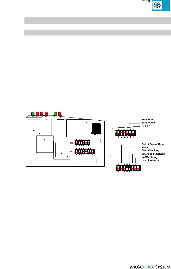
The factory set coupler configuration can be changed using the DIP switches FR and P. The setting is made prior to start-up. Changes to switch settings during running operation does not affect the configuration. This is only read in when switching on the coupler power supply.
The ‘MODBUS coupler/controller’ chapter describes how to remove the enclosure from the coupler to permit settings to be made.
Fig. 5.1: DIP switch arrangement on CPU printed circuit board, coupler
The following is a description of the coupler settings. Here the term ‘Frame’ is frequently used. A ‘Frame’ is a data transmission block.
MODBUS / Configuration |
25 |
15.12.99

5.1.1.1 Standard settings
The coupler is supplied with the following standard settings:
Designation |
Setting |
FR |
FR |
FR |
FR |
FR |
FR |
P1 |
P2 |
P3 |
P4 |
P5 |
P6 |
P7 |
P8 |
Chapt. |
|
|
1 |
2 |
3 |
4 |
5 |
6 |
|
|
|
|
|
|
|
|
|
Baud rate |
9600 Bd |
off |
on |
on |
|
|
|
|
|
|
|
|
|
|
|
5.1.1.2 |
Byte Frame |
No Parity, 8 Bit |
|
|
|
off |
off |
off |
|
|
|
|
|
|
|
|
5.1.1.3 |
|
1 Stop Bit |
|
|
|
|
|
|
|
|
|
|
|
|
|
|
|
End of Frame |
3 x Frame Time |
|
|
|
|
|
|
off |
off |
off |
|
|
|
|
|
5.1.1.4 |
Time |
|
|
|
|
|
|
|
|
|
|
|
|
|
|
|
|
Mode |
RTU mode |
|
|
|
|
|
|
|
|
|
on |
|
|
|
|
5.1.1.5 |
Error Check |
to be processed |
|
|
|
|
|
|
|
|
|
|
on |
|
|
|
5.1.1.6 |
Extended |
without |
|
|
|
|
|
|
|
|
|
|
|
off |
|
|
5.1.1.7 |
Functions |
|
|
|
|
|
|
|
|
|
|
|
|
|
|
|
|
Watchdog |
switched on |
|
|
|
|
|
|
|
|
|
|
|
|
off |
|
5.1.1.8 |
Update |
normal |
|
|
|
|
|
|
|
|
|
|
|
|
|
off |
5.1.1.9 |
Firmware |
operation |
|
|
|
|
|
|
|
|
|
|
|
|
|
|
|
Table 5.1: Standard settings, coupler
5.1.1.2 Baud rate setting
The baud rate is set using DIP switches FR 1 to FR 3.
Baud rate |
Baud rate |
FR1 |
FR2 |
FR3 |
750-312/314 |
750-315/316 |
|
|
|
|
|
|
|
|
150 Bd |
38400 Bd |
off |
off |
off |
|
|
|
|
|
300 Bd |
57600 Bd |
on |
off |
off |
|
|
|
|
|
600 Bd |
115200 Bd |
off |
on |
off |
|
|
|
|
|
1200 Bd |
1200 Bd |
on |
on |
off |
|
|
|
|
|
2400 Bd |
2400 Bd |
off |
off |
on |
|
|
|
|
|
4800 Bd |
4800 Bd |
on |
off |
on |
|
|
|
|
|
9600 Bd |
9600 Bd |
off |
on |
on |
|
|
|
|
|
19200 Bd |
19200 Bd |
on |
on |
on |
|
|
|
|
|
Table 5.2: Baud rates, coupler
The standard setting is 9600 Baud.
26 |
MODBUS / Configuration |
15.12.99