Материал: m013802e_a

List of contents for register 2 |
|
|
1 |
WAGO-I/O SYSTEM ................................................................. |
1 |
1.1 |
Components .................................................................................................. |
1 |
1.2 |
Installation.................................................................................................... |
2 |
1.3 |
Methods of decentralisation ........................................................................ |
6 |
2 |
MODBUS Coupler/Controller................................................... |
9 |
2.1 |
Hardware...................................................................................................... |
9 |
2.2 |
Power supply ................................................................................................ |
10 |
2.2.1 |
Electronic supply voltage............................................................................... |
11 |
2.2.2 |
Supply voltage of the field side...................................................................... |
12 |
2.3 |
Station address ............................................................................................. |
13 |
2.4 |
Mode switch.................................................................................................. |
14 |
2.5 |
Fieldbus connection ..................................................................................... |
15 |
2.5.1 |
RS 485............................................................................................................ |
15 |
2.5.2 |
RS 232............................................................................................................ |
18 |
3 |
Technical data ............................................................................. |
19 |
3.1 |
Dimensions.................................................................................................... |
19 |
3.2 |
Coupler ......................................................................................................... |
20 |
3.3 |
Controller ..................................................................................................... |
21 |
4 |
MODBUS ..................................................................................... |
23 |
5 |
Configuration .............................................................................. |
25 |
5.1 |
Coupler ......................................................................................................... |
25 |
5.1.1 |
Settings........................................................................................................... |
25 |
5.1.1.1 |
Standard settings ............................................................................................ |
26 |
5.1.1.2 |
Baud rate setting ............................................................................................ |
26 |
5.1.1.3 |
Error detection, length of the character string................................................ |
27 |
5.1.1.4 |
End of Frame Time ........................................................................................ |
28 |
5.1.1.5 |
ASCII-/RTU mode......................................................................................... |
28 |
5.1.1.6 |
Error Check.................................................................................................... |
29 |
5.1.1.7 |
Extended Functions........................................................................................ |
29 |
5.1.1.8 |
Watchdog ....................................................................................................... |
30 |
5.1.1.9 |
Update Firmware ........................................................................................... |
30 |
5.1.2 |
Data exchange between MODBUS master and I/O modules ........................ |
31 |
5.1.3 |
Addressing the I/O modules........................................................................... |
32 |
5.1.4 |
Application examples .................................................................................... |
33 |
MODBUS / Introduction |
vii |
|
15.12.99

5.2 |
Controller ..................................................................................................... |
35 |
5.2.1 |
Settings .......................................................................................................... |
35 |
5.2.1.1 |
Standard settings............................................................................................ |
36 |
5.2.1.2 |
Baud rate setting ............................................................................................ |
36 |
5.2.1.3 |
Error detection, length of character string ..................................................... |
37 |
5.2.1.4 |
End of Frame Time........................................................................................ |
38 |
5.2.1.5 |
ASCII-/RTU mode......................................................................................... |
38 |
5.2.1.6 |
Error Check.................................................................................................... |
39 |
5.2.1.7 |
Extended Functions ....................................................................................... |
39 |
5.2.1.8 |
Watchdog....................................................................................................... |
40 |
5.2.2 |
Data exchange between MODBUS master and controller ............................ |
41 |
5.2.2.1 |
Data exchange between MODBUS master and I/O modules ........................ |
42 |
5.2.2.2 |
Data exchange between MODBUS master and PLC functionality ............... |
44 |
5.2.2.3 |
Data exchange between I/O modules and PLC functionality ........................ |
45 |
5.2.2.4 |
Address review .............................................................................................. |
46 |
5.2.3 |
Absolute addresses for inputs, outputs and flags........................................... |
47 |
5.2.4 |
Addressing the I/O modules .......................................................................... |
49 |
5.2.5 |
Application example...................................................................................... |
50 |
5.2.6 |
Controller operating system........................................................................... |
52 |
5.3 |
Common coupler/controller functions....................................................... |
53 |
5.3.1 |
Implemented MODBUS functions ................................................................ |
53 |
5.3.1.1 |
Use of the MODBUS functions..................................................................... |
54 |
5.3.1.2 |
Read Coil Status ............................................................................................ |
55 |
5.3.1.3 |
Read Input Status........................................................................................... |
57 |
5.3.1.4 |
Read Holding Register................................................................................... |
59 |
5.3.1.5 |
Read Input Register ....................................................................................... |
60 |
5.3.1.6 |
Force Single Coil ........................................................................................... |
61 |
5.3.1.7 |
Preset Single Register .................................................................................... |
62 |
5.3.1.8 |
Fetch Comm Event Counter .......................................................................... |
63 |
5.3.1.9 |
Force Multiple Coils...................................................................................... |
64 |
5.3.1.10 |
Preset Multiple Registers............................................................................... |
65 |
5.3.2 |
Watchdog - Fieldbus failure .......................................................................... |
66 |
5.3.3 |
Configuration function .................................................................................. |
70 |
5.3.4 |
Firmware information.................................................................................... |
71 |
5.3.5 |
General registers ............................................................................................ |
72 |
6 |
Start up and Diagnosis ............................................................... |
73 |
6.1 |
Run up and error indications ..................................................................... |
73 |
6.2 |
MODBUS LED ............................................................................................ |
75 |
6.3 |
Starting up the controller with WAGO-I/O-PRO .................................... |
76 |
viii |
MODBUS / Introduction |
15.12.99

7 |
General Conditions.................................................................... |
79 |
7.1 |
Transport and storage conditions ............................................................. |
79 |
7.2 |
Climatic conditions ..................................................................................... |
79 |
7.3 |
Mechanical conditions ................................................................................ |
80 |
7.4 |
Class and degree of protection................................................................... |
81 |
7.5 |
Specifications and test results .................................................................... |
81 |
7.6 |
Electromagnetic compatibility ................................................................... |
82 |
MODBUS / Introduction |
ix |
15.12.99

|
|
|
|
|
|
|
|
|
|
|
|
|
|
|
|
|
|
|
|
|
|
|
|
|
|
x |
MODBUS / Introduction |
15.12.99
1 WAGO-I/O-SYSTEM
1.1Components
The WAGO-I/O SYSTEMÿcomprises of various components which allow the creation of modular and user specific fieldbus nodes for various fieldbusses.
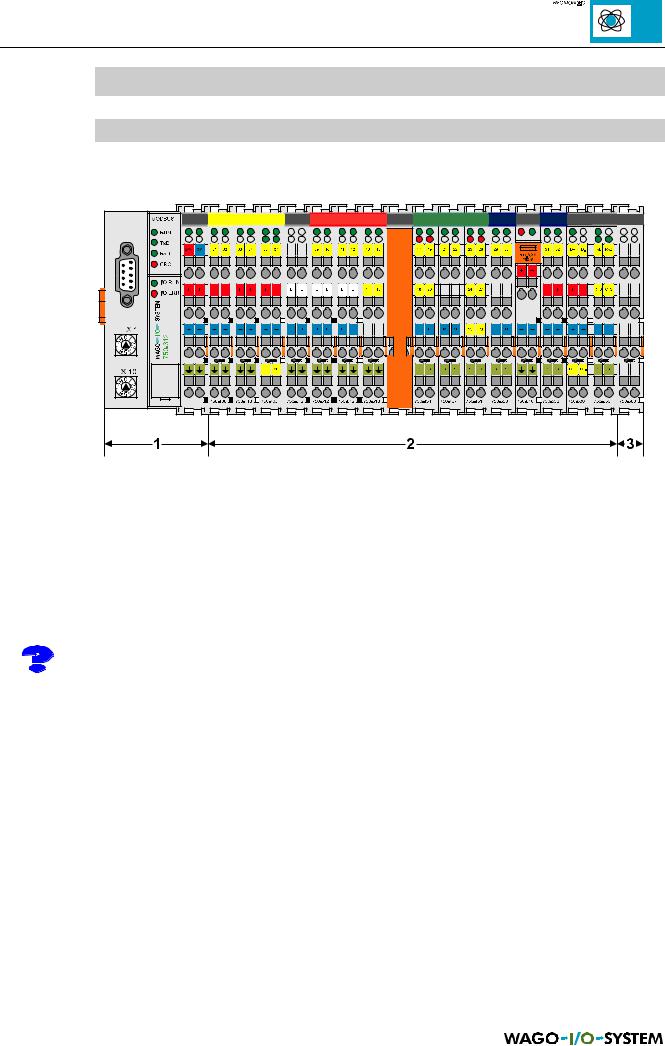
Fig. 1.1: Structure of a fieldbus node with the WAGO-I/O SYSTEM
General:
In all cases a fieldbus node comprises of a fieldbus coupler (1) or a programmable fieldbus controller (1) as head station, a number of I/O modules (2) and an end module (3), which forms the end of the system.
In the following description the term Coupler is used for the fieldbus coupler and the term Controller for the programmable fieldbus controller.
1 – Coupler/Controller:
With its I/O functions the coupler/controller forms the logic operation between the fieldbus used and the field area. All control tasks necessary for the perfect operation of the I/O are performed by the coupler/controller. The connection to different fieldbus systems is made using the corresponding coupler/controller e.g. for PROFIBUS, INTERBUS, CAN, MODBUS etc. A retrofitting to a different fieldbus system by changing the coupler is possible.
As opposed to the coupler the controller is fitted with additional PLC functions. This permits signal pre-processing, which can considerably reduce the data quantity in the network. In the case of a fieldbus failure the controller can process the control program independently. Alternatively the controller can guide the node into a defined condition. Plant modules become independent testable units due to the controller. In the delivered condition, in other words without the user program, the controller behaves as a coupler.
MODBUS / Introduction |
1 |
15.12.99