Материал: m013802e_a
The user can program the controller in accordance with international standards for controller programming, IEC 1131-3 or the corresponding European standard EN 61131-3, in all five languages, IL, LD, FBD, ST and SFC.
The WAGO-I/O-PRO1 programming system is used for the following functions:
∙Programmer setting
∙Controller setting
∙Loading the program in the controller
∙Simulation
∙Test and start-up
∙Visualisation during operation
∙Software documentation
The programming system runs on an IBM compatible PC (for the system requirement please refer to the WAGO-I/O-PRO user manual).
2 – I/O modules
The input and output of the process data is made at the I/O modules. I/O modules are available for various tasks in accordance with varying requirements. Available are digital and analog input and output modules, I/O modules for angle and path measurement as well as communication modules.
The individual I/O modules are described in detail in the following registers.
3 - End module
The node end module is indispensable. It is always fitted as the last module, to guarantee the internal node communication. The end module has no I/O function.
_________________________________
1 WAGO-I/O-PRO User manual, English, Order No. 759-120/000-002
2 |
MODBUS / Introduction |
15.12.99
1.2Installation
All system components can be snapped directly on a carrier rail in accordance with the European standard EN 50022 (TS 35). Installation is simple and space saving. All modules have the same shape to minimise the project commitment.
It is not necessary to observe the order of analog and digital modules when engaging on the rail. The reliable positioning and connection of the coupler/controllers and the individual I/O modules is made using a tongue and groove system. Due to the automatic locking the individual components are securely seated on the rail after installing.
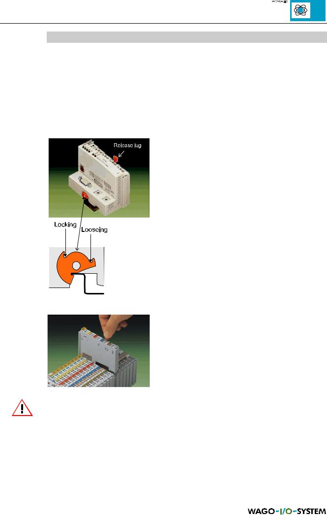
The coupler/controller must be fixed on the carrier rail with the lateral orange coloured locking disk.
The coupler/controller is removed by releasing the locking disk and pulling the release lug which is also orange coloured.
To fix the coupler/controller apply pressure on the upper groove of the locking disk using a screwdriver.
To remove the coupler/controllers release the locking disk by pressing on the bottom groove.
Fig. 1.2: Coupler/controller, locking disk
It is also possible to release an individual I/O module from the unit by pulling an unlocking lug.
Fig. 1.3: Releasing a I/O module
Please note that in this manner the power supply to the field level and the data transfer is interrupted. Ensure that an interruption of the PE will not result in a condition which could endanger a person or equipment!
MODBUS / Introduction |
3 |
15.12.99
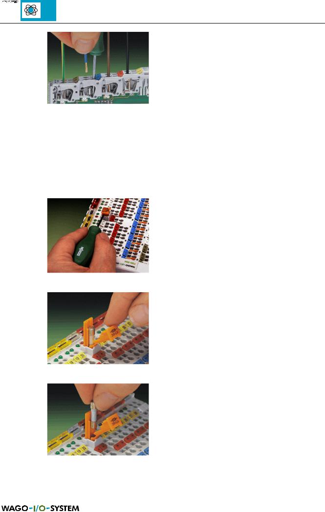
Conductors with a cross section of from 0.08 to 2.5 mm² can be connected using a CAGE CLAMP® to achieve a vibration resistant, fast and maintenance free connection. To actuate the CAGE CLAMP® enter a screw driver or an actuation tool in the opening below the connection. Following this enter the conductor in the corresponding opening. the conductor is
Fig. 1.4: Inserting conductor end clamped securely with the removal of the actuation tool.
The clamping force is automatically adapted to the cross section. The full surface of the cage clamp pressure is applied against the conductor without damaging it. Conductor deformation is compensated for and self-loosening is avoided. The transition point between the conductor and the CAGE CLAMP® is protected against corrosive influences. The connection can be made quickly and is also maintenance free, saving the costs for a periodic checking of terminal connections.
The power supply modules of the WAGO-I/O-SYSTEM are, in part, equipped with a fuse holder. To isolate the following modules from the power supply the fuse holder can be removed. For this insert a screwdriver into one of the slits available on each side and lift the holder.
Fig. 1.5: Removing the fuse holder
The fuses can be removed from or inserted into the holder with the fuse holder cover hinged down. Following this close the cover and push the fuse holder back into the original position.
Fig. 1.6: Opening the fuse holder
Fig. 1.7: Change fuse
4 |
MODBUS / Introduction |
15.12.99
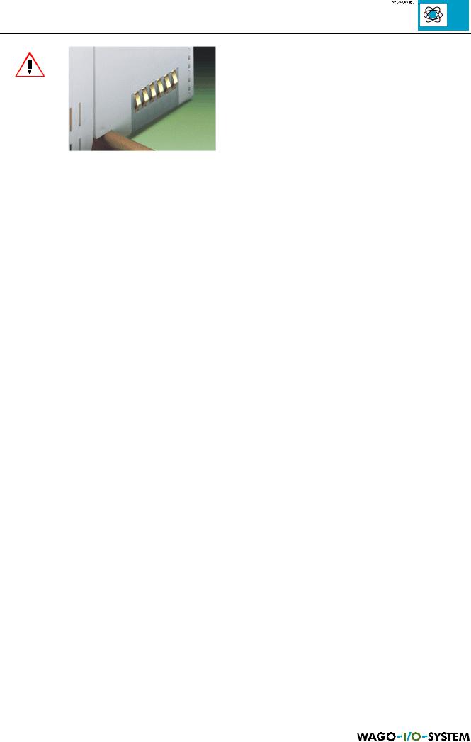
Do not connect the I/O module to gold spring contacts in order to avoid soiling and scratches!
Fig. 1.8: Gold contacts
MODBUS / Introduction |
5 |
15.12.99
1.3Methods of decentralisation
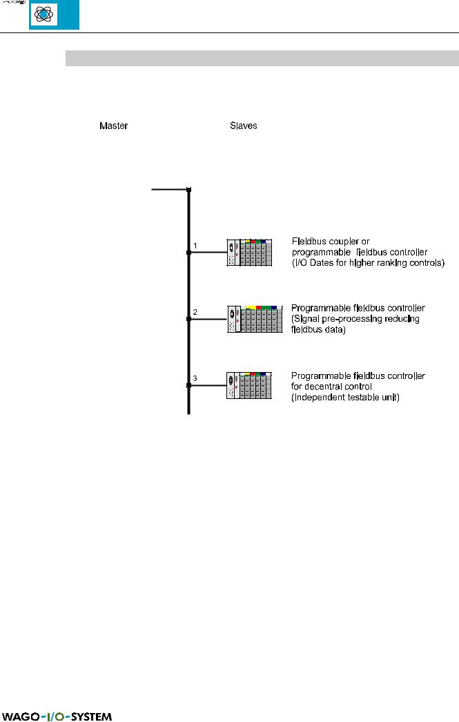
By using the coupler or the controller it is possible to realise various methods for the decentralisation of control tasks.
Fig. 1.9: Decentralisation methods
Central control using a coupler or a controller (1)
The process methods common to date: All input sensor signals are joined in the coupler (Slave) and led to the higher ranking controls (Master) via a bus system. The data generated for signal output in the higher ranking controls reaches the actuators via bus and nodes. The reaction time of the controls is dependent upon the fieldbus.
This principle can be performed in the same manner using the controller.
Signal pre-processing using controller (2)
Certain control tasks, e.g. impulse generation, delays and counts (e.g. quantity), are taken care of on site. The logic operations required are processed in the controller. The bus system only transmits the results of the logic operations as process data to the higher ranking controls. For signal pre-processing the amount of fieldbus data required is less than that required for a central connection.
6 |
MODBUS / Introduction |
15.12.99