Материал: m083300e

142 • Explosive Environments
Classifications meeting the NEC
7.4.3Temperature classes
Electrical components for explosive areas are differentiated by temperature classes:
Temperature classes |
Maximum |
Ignition temperature |
|
surface temperature |
of the combustible materials |
T1 |
450 °C |
> 450 °C |
|
|
|
T2 |
300 °C |
> 300 °C ≤ 450 °C |
|
|
|
T2A |
280 °C |
> 280 °C ≤ 300 °C |
|
|
|
T2B |
260 °C |
> 260 °C ≤ 280 °C |
|
|
|
T2C |
230 °C |
>230 °C ≤ 260 °C |
|
|
|
T2D |
215 °C |
>215 °C ≤ 230 °C |
|
|
|
T3 |
200 °C |
>200 °C ≤ 215 °C |
|
|
|
T3A |
180 °C |
>180 °C ≤ 200 °C |
|
|
|
T3B |
165 °C |
>165 °C ≤ 180 °C |
|
|
|
T3C |
160 °C |
>160 °C ≤ 165 °C |
|
|
|
T4 |
135 °C |
>135 °C ≤ 160 °C |
|
|
|
T4A |
120 °C |
>120 °C ≤ 135 °C |
|
|
|
T5 |
100 °C |
>100 °C ≤ 120 °C |
|
|
|
T6 |
85 °C |
> 85 °C ≤ 100 °C |
|
|
|
D R A F T |
WAGO-I/O-SYSTEM 750 |
2001-02-27 |
PROFIBUS |
Explosive Environments • 143
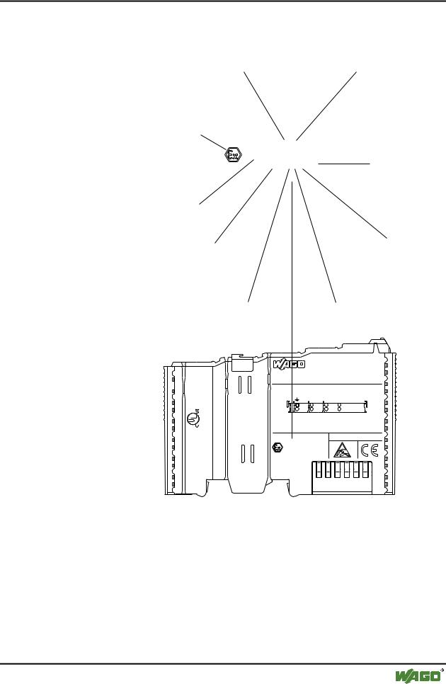
Identification acc. to CENELEC, IEC and ATEX 100a
7.5 Identification acc. to CENELEC, IEC and ATEX 100a
Explosion protection group |
Unit category |
Community symbol for explosion protected electrical components
II 3 G |
|
KEMA 01ATEX1024 X |
|
EEX nA II T4 |
Temperature class |
Approval body and/or number of the examination certificate
Explosion protection group
E = conforming with European standards Ex = explosion protected component
n = Type of ignition |
Extended identification |
ITEM-NO.:750-400
24V DC AWG 28-14 55°C max ambient
CL I DIV Grp. A B C D op temp code T4A
LISTED 22ZA AND 22XM
-02----03 |
4246 |
1- |
2 |
090 |
|
Hansastr. 27 |
2DI 24V DC 3.0ms |
|
|
D-32423 Minden |
0.08-2.5mm2 |
0V 24V DI1
Di2
PATENTS PENDING
II 3 G
KEMA 01ATEX1024 X EEx nA II T4
Fig. 7-1: Example for lateral labeling of bus modules |
|
(750-400, 2 channel digital input module 24 V DC) |
g01xx03e |
WAGO-I/O-SYSTEM 750 |
D R A F T |
PROFIBUS |
2001-02-27 |
144 • Explosive Environments
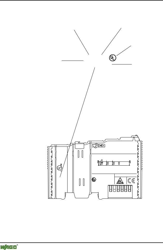
Identification acc. to NEC 500
7.6 Identification acc. to NEC 500
Explosion protection group |
Area of application (zone) |
(condition of use category) |
|
Labeling for
UL listing
C = Canada
US = USA
Explosion group |
CL I DIV 2 |
|
|
Grp. ABCD C |
US |
||
(gas group) |
|||
optemp code T4A |
Temperature class |
||
|
24V DC AWG 28-14 55°C max ambient
CL I DIV Grp. A B C D op temp code T4A
LISTED 22ZA AND 22XM
-02----03 |
4246 |
0- |
2 |
410 |
|
|
ITEM-NO.:750-400 |
Hansastr. 27 |
2DI 24V DC 3.0ms |
|
|
D-32423 Minden |
0.08-2.5mm2 |
0V 24V DI1
Di2
PATENTS PENDING
II 3 G
KEMA 01ATEX1024 X EEx nA II T4
Fig. 7-2: Example for lateral labeling of bus modules |
|
(750-400, 2 channel digital input module 24 V DC) |
g01xx04e |
D R A F T |
WAGO-I/O-SYSTEM 750 |
2001-02-27 |
PROFIBUS |

Explosive Environments • 145
Installation regulations
7.7 Installation regulations
In contrast to the design regulations for electrical components, a standardization of the design regulations on an international scale is not as advanced.
In the Federal Republic of Germany, various national regulations for the installation in explosive areas must be taken into consideration. The basis being the ElexV complemented by the installation regulation DIN VDE 0165/2.91. The following are excerpts from additional VDE regulations:
DIN VDE 0100 |
installation in power plants with rated voltages up to |
|
1000 V |
|
|
DIN VDE 0101 |
installation in power plants with rated voltages above |
|
1 kV |
|
|
DIN VDE 0800 |
installation and operation in tele-communication |
|
plants including information processing equipment |
|
|
DIN VDE 0185 |
lightning protection systems |
|
|
The USA and Canada have their own regulations. The following are excerpts from these regulations:
NFPA 70 |
National Electrical Code Art. 500 Hazordous Loca- |
|
tions |
|
|
ANSI/ISA-RP |
Recommended Practice |
12.6-1987 |
|
|
|
C22.1 |
Canadian Electrical Code |
|
|
WAGO-I/O-SYSTEM 750 |
D R A F T |
PROFIBUS |
2001-02-27 |

146 • Explosive Environments
Installation regulations
Danger
For components with Ex approval please observe the following information:
A.This equipment is exclusively suitable for applications in Class I, Part 2, Group A, B, C, D or in non-explosive areas.
B.Explosion risk -
The substitution/replacement of components may call the suitability for Class I, Part 2 into question.
C.Only disconnect the equipment when the power supply has been switched off or the area is known to be a non-explosive area.
D.The specifications on fuses, voltage and rated current are printed on the fuse holder of the power supply modules.
Proof of certification is available on request.
D R A F T |
WAGO-I/O-SYSTEM 750 |
2001-02-27 |
PROFIBUS |