Материал: m083300e

132 • I/O Modules
List of Digital Input Modules
4 I/O Modules
4.1 Digital Input Modules
4.1.1List of Digital Input Modules
4.1.2750-414 [4 DI 5 V 0,2ms]
4.2 Digital Output Modules
4.2.1List of Digital Output Modules
4.3 Analog Input Modules
4.3.1List of Analog Input Modules
4.4 Analog Output Modules
4.4.1List of Analog Output Modules
4.5 ...
D R A F T |
WAGO-I/O-SYSTEM 750 |
2001-02-27 |
PROFIBUS |

PROFIBUS • 133
Description
5 PROFIBUS
5.1Description
5.2Topology
5.3Wiring
On the PROFIBUS with RS 485 transmission technology all devices are connected in a line structure. The bus line comprises of a twisted and screened pair of wires.
The fieldbus line is specified in EN 50 170 as a line type A and must provide certain line parameters. The line type B also described in the EN 50 170 is an old type and should no longer be used.
Parameter |
Value |
Wave resistance |
135 ... 165 Ω |
|
|
Operating capacity |
< 30 pF/m |
|
|
Loop resistance |
110 Ω/km |
|
|
Wire diameter*) |
> 0.64 mm |
Wire cross section*) |
> 0.34 mm2 |
*) The wire cross sections used must conform with connection possibilities on the bus plug.
Line type A allows maximum line lengths for a bus segment dependent upon the transmission speed.
Transmission speed |
|
Max. bus segment length |
9.6 / 19.2 / 45.45 / 93.75 |
kBaud |
1200 m |
|
|
|
187.5 |
kBaud |
1000 m |
|
|
|
500 |
kBaud |
400 m |
|
|
|
1500 |
kBaud |
200 m |
|
|
|
3000 / 6000 / 12000 |
kBaud |
100 m |
|
|
|
The plugs available on the market offer the possibility that arriving and departing data cables can be directly connected to the plug. In this manner drop cables are avoided and the bus plug can be connected to or disconnected from the bus at any time without interrupting the data traffic. A cut-in type bus connection is integrated in these plugs. Due to the capacitative load of the subscribers and the resulting generated line reflection the connection plugs used should have integrated length inductivity. This is indispensable for transmission rates of > 1.5 MBaud.
WAGO-I/O-SYSTEM 750 |
D R A F T |
PROFIBUS |
2001-02-27 |
134 • PROFIBUS
Wiring
9-pol. D-SUB |
|
Weitere |
|||||
Stecker |
|
|
Feldbusteilnehmer |
||||
|
|
|
|
|
|
|
|
6 |
|
|
|
|
|
|
|
|
|
|
|
|
|||
2 |
|
|
|
RxD/TxD-P |
|
|
|
3 |
|
|
|
|
Pin 3 - B-Leitung |
||
4 |
|
|
|
|
|
||
|
|
|
|
|
|
||
|
|
|
|
|
|
||
1 |
|
|
|
|
|
|
|
|
|
|
|
|
|||
9 |
|
|
|
RxD/TxD-N |
|
Pin 8 - A-Leitung |
|
8 |
|
|
|
|
|||
7
5
Längsinduktivität = 110 nH
Fig. 5-1: Bus connection
9-pol. D-SUB Stecker
mit Busabschluss
|
|
|
VP |
|
|
|
|
|
6 |
|
|
|
|
|
|
|
|
|
|||
|
|
|
|
|
|
|
|
|
||
|
390 |
|
RxD/TxD-P |
|
|
|
|
2 |
||
|
|
|
|
|||||||
|
|
|
|
|
|
|
3 |
|||
|
|
|
|
|
|
|
||||
|
|
|
|
|
|
|
4 |
|||
|
|
|
||||||||
|
|
|
|
|
|
|
|
|
||
220 |
|
|
|
|
|
|
|
1 |
||
|
|
|
|
|
||||||
|
RxD/TxD-N |
|
|
|
|
|
9 |
|||
|
|
|
|
|
|
|||||
|
|
|
|
|
|
|
|
|||
|
|
|
|
|
|
|||||
|
|
|
|
|
|
|
|
8 |
||
|
|
|
|
|
|
|
|
|
|
|
390 |
|
DGND |
|
|
|
|
|
7 |
||
|
|
|
|
|
|
5 |
||||
|
|
|
|
|
|
|||||
|
|
|
|
|
|
|
|
|||
|
|
|
|
|
|
|||||
|
|
|
|
|
|
|
|
|
|
|
g012102d
Note
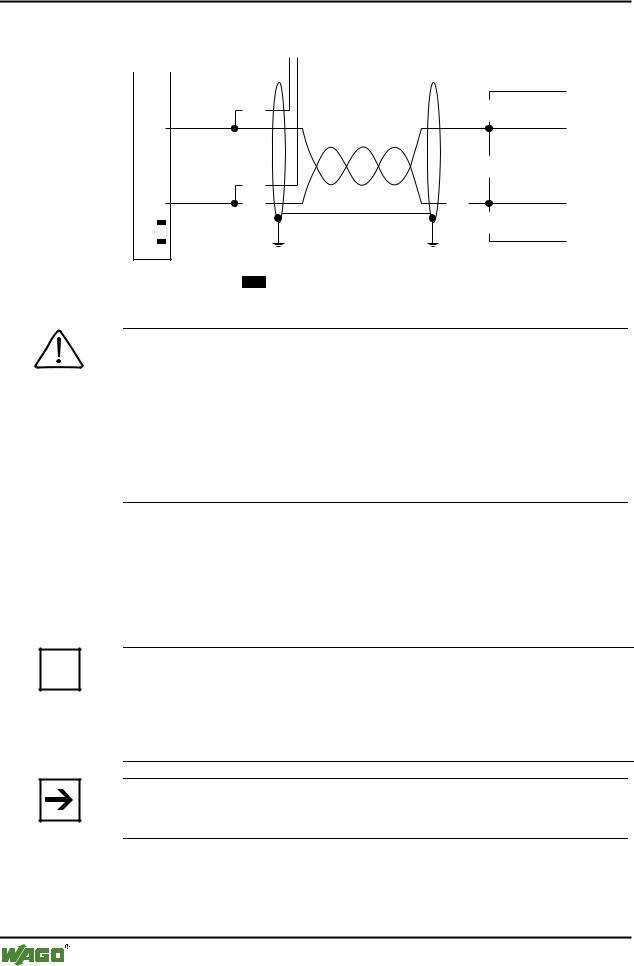
When connecting the subscriber ensure that the data lines are not mixed up. The bus termination at the start and end of the bus line must be installed. The bus connection requires the supply voltage VP from the device. For this reason ensure that the slave unit installed on the bus termination, is always supplied with voltage.
Due to the integrated length inductivity in the connection plug ensure that the plug is installed without connected field devices as the missing capacity of the device could cause transmission faults.
In order to achieve a high disturbance resistance of the system against electromagnetic radiated interference ensure that a screened PROFIBUS cable is used. Where possible connect the screen at both ends with good conduction and using large surface area screen clips. In addition ensure that the cables are laid separated from all power line cables if possible. With a data rate of ≥1.5 Mbit/s ensure that spur lines are avoided.
Further information
i The PNO provides further documentation for its members in INTERNET. Cable specification information can be obtained from, for example, the „Installation Guideline for PROFIBUS-FMS/DP", 2.112
http://www.profibus.com/
Note
WAGO offers this screen connection system for the optimum connection between fieldbus screening and function earth.
D R A F T |
WAGO-I/O-SYSTEM 750 |
2001-02-27 |
PROFIBUS |

Configuration example • 135
NETCON
6 Configuration example
6.1 NETCON
in preparation
6.2 Step 7
in preparation
6.3 COM Profibus
in preparation
WAGO-I/O-SYSTEM 750 |
D R A F T |
PROFIBUS |
2001-02-27 |

136 • Explosive Environments
Foreword
7 Explosive Environments
7.1 Foreword
Today’s development shows that many chemical and petrochemical companies have production plants and process automation machines in operation which use gas-air, vapor-air and dust-air mixtures which can be explosive. For this reason, the electrical components used in such plants and systems must not pose a risk of explosion resulting in injury to persons or damage to property. This is backed by law, directives or regulations, on a national and international scale. WAGO-I/O-SYSTEM 750 is designed for use in zone 2 explosive environments, for which reason the following basic explosion protection related terms have been defined.
7.2 Protective measures
Primarily, explosion protection describes how to prevent the formation of an explosive atmosphere. For instance by avoiding the use of combustible liquids, reducing the concentration levels, ventilation measures, to name but a few. But there are a large number of applications, which do not allow the implementation of primary protection measures. In such cases, the secondary explosion protection comes into play. Following is a detailed description of such secondary measures.
7.3 Classification meeting CENELEC / IEC
The specifications outlined here are valid for use in Europe and are based on the following standards: EN50... of CENELEC (European Committee for Electrotechnical Standardisation) and IEC79-... of IEC (International Electrotechnical Commission):
7.3.1Division into zones
Explosive environments are areas arein which the atmosphere can potentially become explosive. The term explosive means a special mixture of ignitable substances existing in the form of air-borne gases, fumes, mist or dust under atmospheric conditions which, when heated beyond a tolerable temperature or subjected to an electric arc or sparks, can produce explosions. Explosive zones have been created to describe the concentrations level of an explosive atmosphere. This division is based on the probability of an explosion occurring.
D R A F T |
WAGO-I/O-SYSTEM 750 |
2001-02-27 |
PROFIBUS |