Материал: m083300e
2 • Important comments
1.2 Scope
This manual describes the field bus independent WAGO-I/O-SYSTEM 750 with the fieldbus coupler for PROFIBUS.
Item-No. |
Components |
750-333 |
PROFIBUS DP/DPV1 12 MBd |
|
|
750-833 |
Contr. PROFIBUS DP/DPV1 12 MBd |
|
|
750-xxx |
I/O Modules |
|
|
1.3 Symbols
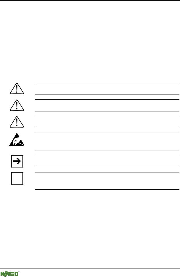
Danger
Always observe this information to protect persons from injury.
Warning
Always observe this information to prevent damage to the device.
Attention
Marginal conditions must always be observed to ensure smooth operation.
ESD (Electrostatic Discharge)
Warning of damage to the components by electrostatic discharge. Observe the precautionary measure for handling components at risk.
Note
Routines or advice for efficient use of the device and software optimisation.
More information
i References to additional literature, manuals, data sheets and INTERNET pages
D R A F T |
WAGO-I/O-SYSTEM 750 |
2001-02-27 |
PROFIBUS |

Important comments |
• 3 |
1.4 Font conventions
Italic
Italic
\
END
< >
Courier
Names of path and files are marked italic
e. g.: C:\programs\WAGO-IO-CHECK
Menu items are marked as bold italic e. g.: Save
A backslash between two names marks a sequence of menu items
z. B.: File\New
Press bottons are marked as bold with small capitals e. g.: ENTER
Keys are marked bold within angle brackets e. g.: <F5>
Program code are printed with the font Courier. e. g.: END_VAR
1.5 Number notation
Number Code |
Example |
Note |
Decimal |
100 |
normal notation |
|
|
|
Hexadecimal |
0x64 |
C notation |
|
|
|
Binary |
'100' |
Within ', |
|
'0110.0100' |
Nibble separated with dots |
|
|
|
WAGO-I/O-SYSTEM 750 |
D R A F T |
PROFIBUS |
2001-02-27 |

4 • Important comments
1.6 Abbreviation
DI |
Digital Input |
DO |
Digital Output |
I/O |
Input/Output |
ID |
Identifier |
PFC |
Programmable Fieldbus Controller |
PFC-PI |
Programmable Fieldbus Controller - Process Images |
PFC-RTS |
Programmable Fieldbus Controller - Runtime system |
PI |
Process Images |
PLC |
Programmable Logic Control |
AO |
Analog Output Module |
AI |
Analog Input Module |
SM |
Special Module |
D R A F T |
WAGO-I/O-SYSTEM 750 |
2001-02-27 |
PROFIBUS |
WAGO-I/O-SYSTEM 750 • 5
System Description
2 WAGO-I/O-SYSTEM 750
2.1 System Description
2.1.1General
The WAGO-I/O-SYSTEM 750 consists of various components which are capable of providing modular and application specific fieldbus nodes for various fieldbusses.
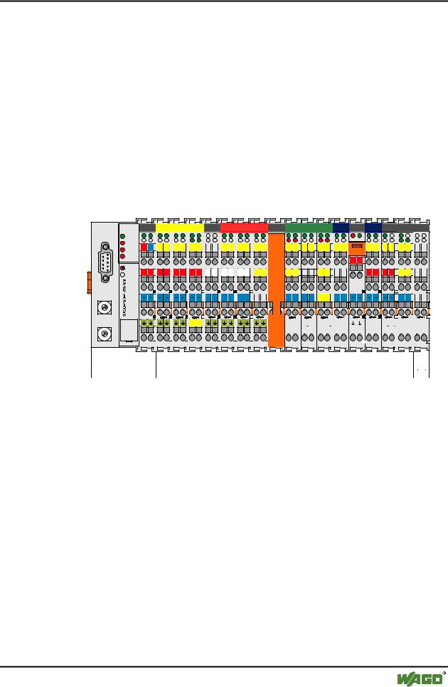
A fieldbus node (short: Node) consists in principle of a fieldbus coupler (short: Coupler) ) or Programmable Fieldbus Controller (short: Controller) ) (1) at the front end, a number of special I/O modules (2) and a End Module (3) which is placed at the other end.
|
X 1 |
|
9 |
01 |
|
|
2 |
|
8 |
|
3 |
7 |
|
|
65 |
4 |
|
|
||
X 10 |
||
9 |
01 |
|
|
2 |
|
8 |
|
3 |
7 |
|
|
65 |
4 |
|
|
||
PROFIBUS |
|
|
|
|
|
|
|
|
|
|
|
|
|
|
RUN |
|
|
|
|
|
|
|
|
|
|
|
|
|
|
BF |
|
|
|
|
|
|
|
|
|
|
|
|
|
|
24V |
0V |
01 |
02 |
03 |
04 |
05 |
07 |
|
09 |
10 |
11 |
12 |
13 |
15 |
DIA |
|
|
|
|
|
|
|
|
|
|
|
|
|
|
BUS |
|
|
|
|
|
|
|
|
|
|
|
|
|
|
I/O |
|
|
|
|
|
|
|
|
|
|
|
|
|
|
+ + + + + + + + |
L L |
L |
L |
L |
L |
14 |
16 |
|||||||
|
N |
N |
N |
N |
N |
N |
750-333 |
|
|
|
|
|
|
06 |
08 |
|
|
|
|
|
 750-400
  750-410
  750-403 750-612
  750-512
  750-512
  750-513
17 |
19 |
21 22 |
23 |
26 |
29 30 |
31 |
32 |
D+ |
D- |
TxD |
RxD |
|
|
|
|
|
max. 6,3 A |
|
|
|
|
|
|
|
|
|
|
|
250 V |
|
|
|
|
|
|
|
|
|
|
|
+ |
+ |
|
|
|
|
|
18 |
20 |
|
24 |
27 |
|
+ |
+ |
+ |
+ |
RTS |
CTS |
M |
M |
M |
M |
25 |
28 |
M |
M |
M |
M |
|
S |
S |
|
S |
S |
|
S |
S |
|
S |
S |
|
|
|
|
S |
S |
|
CL+ |
CL- |
|
S |
S |
|
|
|
|
|
|
|
|
|
|
|
|
|
|
|
|
|
|
||||||||||||||
|
|
|
|
|
|
|
|
|
|
|
|
|
|
|
|
|
|
|
|
|
|
|
|
|
|
|
|
|
|
|
|
|
|
|
|
|
|
|
|
|
|
|
|
|
|
|
|
|
|
|
|
|
|
|
|
750-454 |
750-467 |
750-461 |
750-550 |
750-610 |
|
750-552 |
750-630 |
750-650 |
750-600 |
|
 1
1
 2
2
 3
3
Fig. 2-1: Setting up a fieldbus node for PROFIBUS |
g01x101x |
WAGO-I/O-SYSTEM 750 |
D R A F T |
PROFIBUS |
2001-02-27 |

6• WAGO-I/O-SYSTEM 750
System Description
2.1.2Coupler/Controller (1)
The Coupler/Controller forms the link between the fieldbus and the field devices with their I/O functions. All control functions required for the faultless operation of the I/O functions are carried out by the Coupler/Controller. The connection to different fieldbus systems is established by each of the corresponding Coupler/Controller, e.g. for PROFIBUS, INTERBUS, CAN, MODBUS etc. In this way a change of the fieldbus system is possible.
The programmable fieldbus controller 750-833 combines the PROFIBUS DP functionality of the fieldbus coupler 750-333 with the functionality of a Programmable Logic Control (PLC). Programming of the application is done with WAGO-I/O-PRO in accordance with IEC 61131-3, covering all 5 programming languages. The programmer can access all fieldbus and I/O data.
Characteristics and use of the Controllers:
•The use of decentralized control can better support a PLC or PC
•Signal pre-processing reduces fieldbus transmissions
•Complex applications can be divided into multiple tasks
•Tasks can be prioritized
•Peripheral equipment can be controlled directly, resulting in faster system response times
•Programmable response in the event of a fieldbus failure
•Simple, self-sufficient control
D R A F T |
WAGO-I/O-SYSTEM 750 |
2001-02-27 |
PROFIBUS |