Материал: part17

Внимание! Если размещение файла нарушает Ваши авторские права, то обязательно сообщите нам

Page 966​

DICOM PS3.17 2020a - Explanatory Information​

•​ST 2110-21: Traffic Shaping Uncompressed Video;​

•​ST 2110-30: Uncompressed PCM audio;​

•​ST 2110-40: Ancillary data.​

TheST2110familyofstandardsexpandsovertimeandthecorrespondingDICOMcomponentsmayconsideradoptingtheseextensions​ (e.g., compressed video, large metadata support…).​

Thesystemisintendedtobeextensibletoavarietyofessencetypes,itspivotalpointbeingtheuseoftheRTPprotocol.Inthissystem,​ essence streams are encapsulated separately into RTP before being individually forwarded through the IP network.​

A system is built from devices that have senders and/or receivers. Streams of RTP packets flow from senders to receivers, however​ senders have no explicit awareness or coordination with the receivers. RTP streams can be either unicast or multicast, in which case​ multiple receivers can receive the stream over the network.​

Devices may be adapters that convert from/to existing standard interfaces like HDMI or SDI, or they may be processors that receive​ one or more streams from the IP network, transform them in some way and transmit the resulting stream(s) to the IP network. Cam-​ erasandmonitorsmaytransmitandreceiveelementaryRTPstreamsdirectlythroughanIP-connectedinterface,eliminatingtheneed​ for legacy video interfaces.​

Proper operation of the ST 2110 environment relies on a reliable timing infrastructure that has been largely inspired by the one used​ in AES67 for Audio over IP.​

Inter-stream synchronization relies on timestamps in the RTP packets that are sourced by the senders from a common Reference​ Clock. The Reference Clock is distributed over the IP network to all participating senders and receivers via PTP (Precision Time​ Protocol version 2, IEEE 1588-2008).​

Synchronization at the receiving device is achieved by the comparison of RTP timestamps with the common Reference Clock.​

DICOM devices, which typically support NTP, will need to handle PTP to use this functionality, which may involve hardware changes.​ Each device maintains a Media Clock which is frequency locked to its internal time-base and advances at an exact rate specified for​ thespecificmediatype.Themediaclockisusedbysenderstosamplemediaandbyreceiverswhenrecoveringdigitalmediastreams.​ For video and ancillary data, the rate of the media clock is 90 kHz, whereas for audio it can be 44.1 kHz, 48 kHz, or 96 kHz.​

For each specific media type RTP stream, the RTP Clock operates at the same rate as the Media Clock.​

ST2110-20specifiesaverygenericmechanismforRTPencapsulationofavideoraster.Itsupportsarbitraryresolutions,framerates,​ and introduces a clever pixel packing accommodating an extremely wide variety of bit depths and sampling modes. It is very heavily​ inspired from IETF RFC4175.​

ST 2110-21 specifies traffic shaping and delivery timing of uncompressed video, in order to enable transport of multiple videos on​ the same physical network.​

ST 2110-30 specifies a method to encapsulate PCM digital audio using AES67 to which it applies a number of constraints. AES67 is​ a technical standard for audio over IP and audio over Ethernet. The standard was developed by the Audio Engineering Society.​

ST 2110-40 specifies a simple method to tunnel packets of SDI ancillary data present in a signal over the IP network and enables a​ receiver to reconstruct an SDI signal that will embed the ancillary data at the exact same places it occupied in the original stream.​

Sender devices construct one SDP (Session Description Protocol) object per RTP Stream. These SDP objects are made available​ through the management interface of the device, thereby publishing the characteristics of the stream they encapsulate, however no​ methodisspecifiedtoconveytheSDPobjecttothereceiver.ImplementationscanrelyonwebURLs,filesordocumentationonmedia,​ or it can be configured on the receiver from product documentation since it can be relatively static. This SDP object provides the basic​ information a system needs in order to identify the available signal sources on the network.​

It is worth noting that although ST 2110 currently describes the method for transporting video and audio, the same principles may be​ appliedtoothertypesofmediabyselectingtheappropriateRTPpayloadencapsulationscheme,andcomplyingtothegeneralprinciples​ defined by ST 2110-10.​

Some details of the ST 2110-10 are reproduced below for convenience. Refer to the original specifications for implementation.​

The RTP header bits have the following format:​

- Standard -​


DICOM PS3.17 2020a - Explanatory Information​


Page 967​


0

1

2

3

4

5

6

7

8

9

10

11

12

13

14

15

16

17

18

19

20

21

22

23

24

25

26

27

29

30

31


V = 2

P

X


CC


M


PT


sequence number


timestamp


synchronization source (SSRC) identifier


Figure QQQQ-2. RTP Header​

With:​

version (V) : 2 bits​ padding (P) : 1 bit​ extension (X) : 1 bit​ CSRC (CC) : 4 bits​ marker (M) : 1 bit​

payload type (PT)​

sequence number​

timestamp​

SSRC​

Version of RTP as specified in IETF RFC 3550.​

When set the packet contains padding octets at the end as specified in IETF RFC 3550.​

When set the fixed header is followed by an RTP header extension.​

Number of CSRC identifiers as specified in IETF RFC 3550.​

For video it is set to 1 when the RTP packet is carrying the last video essence of a frame or the last​ part of a field as specified in SMPTE ST 2110-20.​

Identifies the format of the payload. For a video or audio payload it is as specified in SMPTE ST 2110-​ 10.​

Increments by one for each RTP data packet sent. It is as specified in IETF RFC 3550.​

Increments by one for each RTP data packet sent. It is as specified in IETF RFC 3550.​

Reflects the sampling instant of the first octet in the RTP data packet. It contains the timestamp as​ specified in SMPTE ST 2110-10.​

Identifies the synchronization source. It is as specified in IETF RFC 3550.​

The RTP header extension bits have the following format:​

0

1

2

3

4

5


6

7

8

9

10

11

12

13

14

15

16

17

18

19

20

21

22

23

24

25

26

27

29

30

31


defined by profile


length


header extension

...


Figure QQQQ-3. RTP Header Extension​

With:​


defined by profile: 16 bits​

It is defined by the type of header extension used.​

length: 16 bits​

Size of the header extension in 32-bits units. It does not include the 4 byte header extension​


("defined by profile" + "length").​

header extension​

The one-byte header extension form is described below. The total size of the header extension is​


a multiple of 4 bytes.​

In complement to the SMPTE ST 2110 family of standards, AMWA (Advanced Media Workflow Association) has authored a recom-​ mendation called NMOS (Networked Media Open Specifications) which specifies the following header extensions:​

PTP Sync Timestamp​ provides an absolute capture or playback timestamp for the Grain essence data, which consists of a​ 48-bit seconds field followed by a 32-bit nanosecond field. The length value in the extension header is​ 9.​

- Standard -​

Page 968​

DICOM PS3.17 2020a - Explanatory Information​

PTP Origin Timestamp​ provides an absolute capture timestamp for the Grain essence data, which consists of a 48-bit seconds​ field followed by a 32-bit nanosecond field. The length value in the extension header is 9.​

Flow Identifier​

a UUID which uniquely identifies the flow. The value is 16 bytes and therefore the length value in the​


extension header is 15.​


Source Identifier​

a UUID which uniquely identifies the source. The value is 16 bytes and therefore the length value in the​


extension header is 15.​


Grain Duration​

identifies the time period for which the video essence within the Grain should be displayed or the time​


period for which the audio essence should be played back, describing the length of a consistent video​


or audio sequence. It is a rational number consisting of a 4 byte numerator and 4 byte denominator.​


The value is 8 bytes and therefore the length value in the extension header is 7. Use of Grain Duration​


is optional.​


Grain Flags​

The Grain Flags are a single byte with the following form:​


0

1

2

3


4

5


6

7


S

E


reserved


Figure QQQQ-4. RTP Grain Flags​

Start flag (S) : 1 bit​

This bit shall be set to 1 in the first packet of the Grain. Otherwise it​


shall be set to 0.​

End flag (E) : 1 bit​

This bit shall be set to 1 in the last packet of the Grain. Otherwise it​


shall be set to 0.​

Reserved: 6 bits​

These bits are reserved for future use and should be set to 0. The​


length value of this extension header is 0.​

- Standard -​

DICOM PS3.17 2020a - Explanatory Information​

Page 969​

RRRR Encapsulated OBJ, 3D Model​

Grouping, & Color (Informative)​

RRRR.1 Overview​

This section explains the encapsulation of a 3D manufacturing model file of the OBJ type inside a DICOM instance. The goal of en-​ capsulating a model rather than transforming the data into a different representation is to facilitate preservation of the 3D file in the​ exact form that it is used with extant manufacturing devices. At the same time encapsulation populates DICOM header elements that​ record clinical information absent from the OBJ format, including unambiguously associating it with the patient for whose care the​ model was created. Encapsulation also makes it possible to link to the images from which the model was derived, even if these came​ from different studies.​

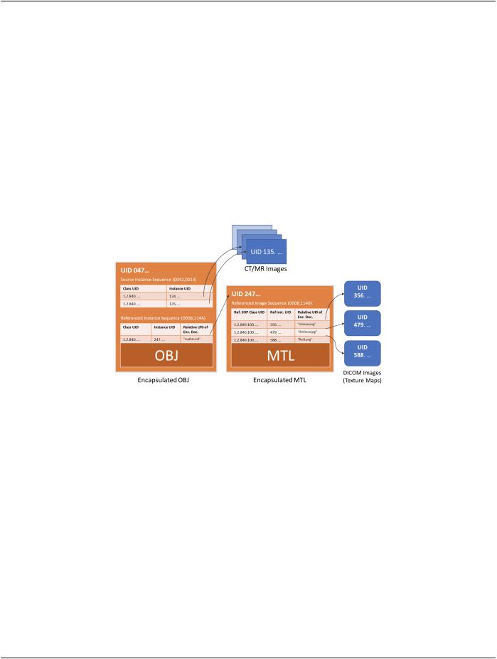
The OBJ encapsulation case is slightly more complicated than that of STL (Annex IIII). The OBJ has supporting files (material library​ and texture maps). The relationship between the multiple original files and the corresponding DICOM instances is shown in Fig-​ ure RRRR.1-1.​

Figure RRRR.1-1. Relationship between OBJ, MTL and Texture Map image files and corresponding​ DICOM Instances​

RRRR.2 Example Encoding of OBJ & MTL​

This Section contains example excerpts for encoding OBJ files and associated preview icons (optional), materials library file (MTL)​ (optional), and texture map images (optional).​

RRRR.2.1 Example A​

A patient, Kevin Franz-Lopez, with Medical Record Number 547892459, will shortly be undergoing a complex partial nephrectomy to​ remove lesions on their left kidney. A 3D manufacturing model (encoded in OBJ) was created to manufacture a surgical planning aid​ representing the patient's unique anatomy.​

AmodelwasconstructedfromaCTdataset(CT1).ThemodelwascreatedonJuly16,2017at1:04:34PM.Themodelwasexpressed​ as a single OBJ file (kidneymodel.obj) which makes use of two texture maps encoded using PNG (ntissue.png and fluid.png) and one​ texture map encoded using JPEG (distissue.jpg). The relationship between the OBJ and texture maps is captured in the materials​ list file (matlist.mtl). This set of files corresponds to the Encapsulated MTL and DICOM Images elements in Figure RRRR.1-1.​

A preview icon was created showing the rendered 3D object for inclusion with the OBJ file when encapsulated.​

Table RRRR.2-1 shows the Encapsulated OBJ.​

- Standard -​

Page 970​ DICOM PS3.17 2020a - Explanatory Information​

Table RRRR.2-1. Encapsulated OBJ Example A​

Attribute Name​

Tag​

Example Value​

Comments​

Content Date​

(0008,0023)​

20170716​


Acquisition DateTime​

(0008,002A)​

20170716 13:00:34​


Content Time​

(0008,0033)​

13:00:34​


...​


Modality​

(0008,0060)​

M3D​


...​


Series Description​

(0008,103E)​

Nephrectomy Planning Models​

Referenced Instance Sequence​

(0008,114A)​


%item​


>Referenced SOP Class UID​

(0008,1150)​

1.2.840.10008.5.1.4.1.1.104.5​Encapsulated MTL file SOP​


class​

>Referenced SOP Instance UID​

(0008,1155)​

2.999.89235.5951.35894.751​UIDoftheencapsulatedMTLfile​


(see below) supporting this OBJ​


model​

>Relative URI Reference Within​

(0068,7005)​

"matlist.mtl"​

Relative URI that preserved the​

Encapsulated Document​


MTL file's original filename as​


referenced from within the OBJ​


file.​

%enditem​


...​


Patient Name​

(0010,0010)​

Franz-Lopez^Kevin​


Patient ID​

(0010,0020)​

547892459​


...​


Image Laterality​

(0020,0062)​

L​


Burned In Annotation​

(0028,0301)​

YES​

In this example, the creator of​


the model inscribed the patient's​


medicalrecordnumberonaside​


of the model, to avoid the​


possibility of a wrong patient​


error.​

Recognizable Visual Features​

(0028,0302)​

NO​


MIMETypeofEncapsulatedDocument​

(0040,0012)​

model/obj​


%item​


>Referenced SOP Class UID​

(0008,1150)​

1.2.840.10008.5.1.4.1.1.2.1​

Referenced object is an​


Enhanced CT Image Storage​

>Referenced SOP Instance UID​

(0008,1155)​

2.999.89235.5951.35894.153​The multi-frame CT image from​


study CT1​

%enditem​


...​


Measurement Units Code Sequence​

(0040,08EA)​


%item​


(mm, UCUM, "mm")​ %enditem​

...​

- Standard -​

Источник: https://studfile.net/preview/14585770/