Материал: spra118

SPRA118
This asymmetrical limiting has the effect of delaying the start of a fast-to-slow state transition, until the absolute value of I(k) remains constant for some time. This tends to eliminate premature transitions for pulsed input signals, such as switched carrier voiceband data.
2.4.11Adaptive Predictor and Reconstructed Signal Calculator
The primary function of the adaptive predictor is to compute the signal estimate, se (k), from the quantized difference signal, dq (k). Two adaptive predictor structures are used, a sixth order section that models zeros, and a second order section that models poles in the input signal. This dual structure effectively caters for the variety of input signals which might be encountered.
The signal estimate is computed by:
2
Se (k) + ai (k * 1) Sr (k * i) ) Sez (k),
i + 1
Where
6
sez(k) + bi(k * 1)dq(k * i),
i+1
and the reconstructed signal is defined as:
Sr(k * i) + se(k * i) ) dq(k * i)
Both sets of predictor coefficients are updated using a simplified gradient algorithm for the second-order predictor:
al (k) + 1 * 2*8 al (k * 1) ) 3.2*8 sgn[p(k)]sgn[p(k * 1)],
a2(k) + (1 * 2*7)a2(k * 1) ) 2*7 sgn p(k * 2) * f[a1(k * 1) sgn[p(k)sgn[p(k * 1)]},
Where
p(k) + dq(k) ) sez(k),
4a1, |a1| v |
1 |
2 |
|
f(a1) + |
1 |
2sgn(a1), |a1| ¦ |
2 |
|
|
(13)
(14)
(15)
(16)
(17)
(18)
and sgn[0] = 1, except sgn[p(k–i)] is defined to be 0 only if p(k–i) = 0 and i = 0, with the stability constraints:
|a2(k)| v 0.75 and |a1(k) v 1 * 2*4 * a2(k) |
(19) |
If tr (k) = 1 (see section 2.4.12), then a1 (k) = a2 (k) = 0. |
|
For the sixth-order predictor: |
|
bl (k) + 1 * 2*8 bl (k * 1) ) 2*7 sgn dq (k) sgn dq (k * i) , |
(20) |
for i = 1, 2, ..., 6. |
|
G.726 Adaptive Differential Pulse Code Modulation (ADPCM) on the TMS320C54x DSP |
13 |

SPRA118
For 40-Kbps coding, the adaptive predictor is changed to decrease the leak factor used for zeros coefficient operation. In this case, the previous equation becomes:
bl (k) + 1 * 2*9 bl (k * 1) ) 2*7 sgn dq (k) sgn dq (k * i) , |
(21) |
If tr (k) = 1 (see section 2.4.12), then b1 (k) = b2 (k) = ... = b6 (k) = 0. |
|
As stated above, sgn[0] = 1, except sgn[dq (k–i)] is defined to be 0 only if dq (k–i) = 0 and i = 0. Note that bi (k) is implicitly limited to $ 2.
2.4.12Tone and Transition Detector
To improve performance for signals originating from frequency shift keying (FSK) modems operating in the character mode, a two-step detection process is defined. First, partial band signal (that is, tone) detection is invoked so that the quantizer can be driven into the fast mode of adaptation:
1, a2 (k) ¦ * 0.71875 |
(22) |
td (k) * 0, otherwise |
|
In addition, a transition from a partial band signal is defined so that the predictor coefficients can be set to zero, and the quantizer can be forced into the fast mode of adaptation:
1, a (k 1) |
|
0.71875 and d |
|
(k) |
|
24.2yl(k*1) |
(23) |
tr (k) * 0, otherwise2 * |
¦ * |
|
q |
|
§ |
|
|
2.5Decoder Description
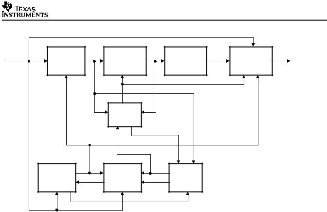
Figure 3 is a block schematic of the decoder. A functional description of each block is given in section 2.5.1 through section 2.5.7.
14 G.726 Adaptive Differential Pulse Code Modulation (ADPCM) on the TMS320C54x DSP
SPRA118
ADPCM |
I(k) |
Inverse |
dq(k) |
Reconstructed |
sr(k) |
Output PCM |
sp(k) |
Synchronous |
sd(k) |
PCM |
|
Adaptive |
Signal |
Format |
Coding |
||||||||
Input |
|
|
|
|
|
Output |
|||||
|
Quantizer |
Calculation |
|
Conversion |
|
Adjustment |
|
||||
|
|
|
|
|
|
||||||
|
|
|
|
se(k) |
|
|
|
|
|
|
|
|
|
|
|
Adaptive |
|
|
|
|
|
|
|
|
|
|
|
Predictor |
|
|
|
|
|
|
|
|
|
|
|
a2(k) |
|
|
|
|
|
|
|
|
|
Quantizer |
y(k) |
Adaptation |
tr(k) |
Tone and |
|
|
|
|
|
|
|
Scale factor |
al(k) |
Speed |
td(k) |
Transition |
|
|
|
|
|
|
|
Adaptation |
Control |
Detection |
|
|
|
|
|||
|
|
|
|
|
|
|
|
||||
|
|
yl(k) |
|
|
|
|
|
|
|
||
Figure 3. Decoder Block Schematic
2.5.1Inverse Adaptive Quantizer
The function of this block is described in section 2.4.8.
2.5.2Quantizer Scale Factor Adaptation
The function of this block is described in section 2.4.9.
2.5.3Adaptation Speed Control
The function of this block is described in section 2.4.10.
2.5.4Adaptive Predictor and Reconstructed Signal Calculator
The function of this block is described in section 2.4.11.
2.5.5Tone and Transition Detector
The function of this block is described in section 2.4.12.
2.5.6Output PCM Format Conversion
This block converts the reconstructed uniform PCM signal, sr(k , into an A-law or m-law PCM signa,l sp(k), as required.
2.5.7Synchronous Coding Adjustment
The synchronous coding adjustment prevents cumulative distortion occurring on synchronous tandem codings (ADPCM, PCM, ADPCM, etc. digital connections), when:
G.726 Adaptive Differential Pulse Code Modulation (ADPCM) on the TMS320C54x DSP |
15 |

SPRA118
1.The transmission of the ADPCM and the intermediate 64 Kbps PCM signals is error free, and,
2.The ADPCM and intermediate 64-Kbps PCM bit streams are not disturbed by digital signal processing devices.
If the encoder and decoder have different initial conditions (as may occur after switching, for example), then the synchronous tandeming may take time to establish. Furthermore, if this property is disturbed, or not acquired initially, then it may be recovered for those signals of sufficient level with spectra that occupy the majority of the 200 Hz to 3400 Hz band (that is, speech, 4800-bit/s voiceband data).
When a decoder is synchronously connected to an encoder, the synchronous coding adjustment block estimates quantization in the encoder. If all state variables in both the decoder and the encoder have identical values, and there are no transmission errors, the forced equivalence of both 4-bit quantizer output sequences for all values of k ensures the property of non-accumulation of distortion.
This is accomplished by first converting the A-law or m-law signal, sp (k), to a uniform PCM signal, slx (k), and then computing a difference signal, dx (k):
dx (k) |
+ slx (k) * se (k) , |
(24) |
||
The difference signal, dx (k), is then compared to the ADPCM quantizer decision interval, |
|
|||
determined by I(k) and y(k). the signal sd (k) is then defined as follows: |
|
|||
|
s)p |
(k), |
dx (k) ¦ lower interval boundary |
(25) |
sd (k) |
+ s*p |
(k), |
dx (k) w upper interval boundary |
|
sp (k) , otherwise
Where
sd (k) is the output PCM codeword of the decoder
*
s p (k) is the PCM codeword that represents the next, more positive, PCM output level. When
)
sp(k) represents the most positive output level, then s p (k) is constrained to be the value sp (k).
*
s p (k) is the PCM codeword that represents the next, more negative, PCM output level. When
*
sp(k) represents the most negative output level, then s p (k) is constrained to be the value sp (k).
3 Useful Features of the C54x for G.726 ADPCM
The typical application for the C54x is for vocoders that deal with a large number of samples at the same time. Application-oriented instructions, such as LMS, FIRS, SQUR, CMPS, or instruction with parallel load/store, do not take place naturally in the ADPCM algorithm. On the other hand, instructions, such as EXP, NORM, MIN, MAX, are often very useful for this purpose. More generally, the ADPCM algorithms benefit from the enhanced architecture of the C54x, which also provides advantages in general purpose applications. The following list sums up the
16 G.726 Adaptive Differential Pulse Code Modulation (ADPCM) on the TMS320C54x DSP

SPRA118
principal features of the C54x used for the CCITT ADPCM algorithm:
•The two accumulators often make it possible to perform parallel treatments and decrease the number of memory accesses (for temporary storage).
•The eight auxiliary registers, which are all simultaneously active, simplify the use of indirect addressing.
•The 40-bit ALU makes it possible to avoid overflow when shifting the accumulator (used in floating-point multiplication when scaling the result).
•Dual data-memory access, using the two or three data buses, makes some calculations faster (used in quantization routine). Also, dual data-memory operand (when used in indirect addressing) allows some instructions to have a one-word length instead of two (in particular load, store, add, sub with left shift), which makes them one-cycle instructions.
•Circular addressing is easy to use. In fact, circular addressing is specified in the instruction word. Moreover, the corresponding buffer is automatically determined (using its memory location), simply by specifying its size (value of the BK register). Two circular buffers would be implemented for the delayed variables dq(k-i) and sr(k-i).
•Long-word arithmetic capability will be used for the variable yl(k) (that requires more precision). It will be used as dual 16-bit operand, when two adjacent variables are calculated (for example, initialization of predictor coefficients, if a transition is detected).
•On-chip data-ROM capability, allows the storage of large tables of constant values, giving the possibility of data addressing.
•The integrated compare unit provides two particularly useful instructions, MIN and MAX. These instructions allow the limitation of the different coefficients, with a minimum of cycles.
•The EXP instruction makes it unnecessary to perform a iterative search for the most significant bit. It is used for floating-point conversion (G.726 ADPCM requires floating-point multiplication for the predictor filters), as well as for log-conversion (before quantizing, and for log-PCM compression). The NORM instruction is often associated with EXP to normalize a variable.
Now, you will see modules whose implementation on the C54x requires some comment.
3.1Input/Output PCM Format Conversions
The ADPCM algorithm works with actual linear PCM inputs/outputs, while the standard format for digital telephony is either A or m-law, which are logarithmic laws of quantization. The CCITT gives these conversion laws in the G.711 recommendation. However, linear/logarithmic PCM conversions are included in the CCITT ADPCM recommendation (G.726) to make the PCM inputs/outputs consistent with the algorithm. There are two reasons for this:
First, a word converted from A-law PCM has only 13 bits, while one word produced from m-law is a 14-bit word. The ADPCM algorithm works with a resolution of 14 bits for PCM input words. To avoid the loss of precision, PCM words coming from A-law are also scaled into 14-bit words.
C54x is a trademark of Texas Instruments.
G.726 Adaptive Differential Pulse Code Modulation (ADPCM) on the TMS320C54x DSP |
17 |