Материал: [2.1] 3D Imaging, Analysis and Applications-Springer-Verlag London (2012)
3 Active 3D Imaging Systems |
129 |
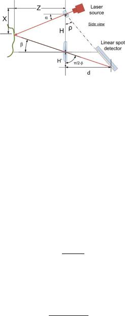
Fig. 3.19 Scheimpflug geometry for a point-based triangulation sensor. The baseline is H . The projection and collection angles are α and β respectively. The angle between the photo-detector and the collecting lens is ρ. Finally, d and H are respectively the distance along the Z-axis and X-axis between the lens optical center and the position of the laser spot on the detector. Figure courtesy of NRC Canada
3.8.3 Scheimpflug Condition
As explained previously, a large lens diameter will induce a small focusing range. This affects all triangulation-based 3D cameras and many of them use the Scheimpflug condition in order to mitigate the impact of this reduced focusing range [16]. In order to simplify the discussion, the Scheimpflug condition will be presented for a point-based scanner. Nevertheless, it could be used with profile-based and areabased scanners. Figure 3.19 shows an optical geometry based on the Scheimpflug condition for the point-based scanner presented in Sect. 3.2. Note that the optical axis is no longer perpendicular to the photo-detector. The angle between the photodetector and the collecting lens is set to ρ and, as will be shown, this ensures that for a given illumination direction (i.e. angle α) all the points along the laser beam path will be in-focus on the position detector. Using simple trigonometry, one can verify that
d tan ρ = H + H
and |
|
|
|
|
H = |
d |
|
|
. |
|
|
|
||
tan(π/2 |
− |
β) |
||
|
|
|
|
|
where H is a line segment in Fig. 3.19. We obtain
H tan ρ
d =
1 − tan β tan ρ
(3.49)
(3.50)
(3.51)
by substituting Eq. (3.50) in Eq. (3.49). Finally, substituting Eq. (3.51) and Eq. (3.2) in Eq. (3.45), we obtain
cot ρ = |
H − f tan α |
. |
(3.52) |
|
f

130 |
M.-A. Drouin and J.-A. Beraldin |
Thus, for a given α, the angle ρ can be computed such that any point along the laser beam path is in-focus on the position detector. This condition allows one to design a system with a large aperture to increase light collection power. As will be explained next, for a laser-based scanner, this allows the reduction of noise without affecting the focusing range.
3.8.4 Speckle and Uncertainty
In Sect. 3.6.1, the error propagation from image intensity to pixel coordinate was examined for area-based scanners that use phase shift and an expression for the variance σx22 was provided. As shown, the variance σx22 can then be used to compute the uncertainty on the 3D points computed by a triangulation scanner. Here, we give the result of a similar analysis performed for point-based systems that use a laser.
For laser-based system, the value of σx22 depends on the type of laser spot detector used (e.g. CMOS, CCD, lateral-effect photodiode, split diodes), the laser peak detector algorithm, the signal-to-noise ratio (SNR) and the imaged laser spot shape [11]. The laser spot shape is influenced by lens aberrations, vignetting, surface artifacts, etc. In the case of discrete response laser spot sensors, assuming both a high SNR and a centroid-based method for peak detection, the dominant error source will be speckle.
Speckle is the result of the interference of many light waves having the same wavelength but having different phases. Different waves emitted by the projection system are reflected on the object at slightly different positions and thus reach the detector with slightly different phases. The light waves are added together at the detector which measures an intensity that varies. The speckle depends on the surface micro-structure or roughness (of the order of the source wavelength) of the object which is scanned. Note that, speckle noise is more a multiplicative noise source than an additive source. Explicitly, the variance σx22 can be approximated as
σx22 ≈ |
λ2d2 |
(3.53) |
2π Φ2 |
where Φ is the lens aperture diameter, λ is the laser wavelength and d is the distance between the laser spot detector and the collection lens [16]. The effects of speckle on the peak detection have also been studied by [8, 30, 45]. Note that when substituting Eq. (3.53) back into Eq. (3.41), one can verify that the presence of speckle noise caused by a laser does not depend on d . When λ is reduced or when Φ is increased, the uncertainty is reduced. While a large lens diameter reduces the uncertainty, it also limits the focusing range when a Scheimpflug condition is not used.
Note that speckle can be an important error source even for a fringe projection system that uses a low-coherence light source with a relatively long coherence length. The coherence length is proportional to the square of the nominal wavelength of the source and inversely proportional to the wavelength range [45].
3 Active 3D Imaging Systems |
131 |
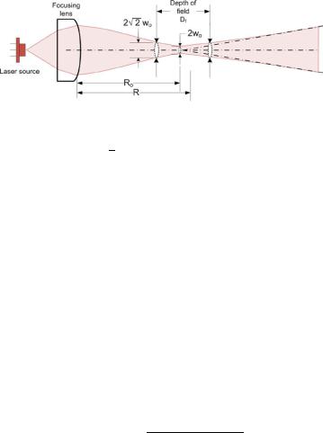
Fig. 3.20 The focus of an actual laser beam is governed by diffraction. We show the case of a focused laser beam with a Gaussian shape transversal profile. The minimum beam diameter is 2w0 and R0 is the distance from√the lens to the point at which the beam diameter is minimal. A maximum beam diameter of 2 2w0 is used to compute the depth of field, Df , of the laser. Figure courtesy of NRC Canada
3.8.5 Laser Depth of Field
Until now, the laser beam and collected ray were assumed to be infinitely thin. Though convenient to explain the basic principles, this is an over-simplification. Taking into account the properties of Gaussian beams associated with lasers is fundamental to understanding the limitations of some 3D laser-based vision systems [17, 20, 55]. As a result of diffraction, even in the best laser emitting conditions, a laser beam does not maintain focus with distance (see Fig. 3.20). Note that in many close-range 3D laser scanners, a focused laser beam is the preferred operating mode. This is a complex topic whose details fall outside the scope of this chapter. Nevertheless, because it is fundamental to understanding the resolution limitations of some 3D imaging systems, we give two important results concerning Gaussian beam propagation. Using the Gaussian beam propagation formula, the beam radius measured orthogonally to the beam axis, denoted by w(R) at the e−2 irradiance contour in the direction of propagation R is
|
= |
|
0 |
|
+ |
|
− |
|
|
|
|
2 |
|
||||||
w(R) |
|
w |
|
1 |
|
|
λ(R R0) |
2 |
(3.54) |
|
|
|
|
|
|
|
|
|
|
where the distance R0 is the distance from the lens to the point at which the beam radius is minimal. The minimum radius is denoted by w0 and λ is the wavelength of the laser source. More details information concerning Eq. (3.54) can be found
in [15, 43, 61]. In accordance with the Rayleigh criterion, the depth of field Df for |
|||||
a focused Gaussian beam is Rmax − Rmin where w(Rmax) = w(Rmin) = |
√ |
|
|
||
2w0 and |
|||||
Rmin < Rmax and explicitly, |
|
|
|
|
|
|
2π w2 |
|
|
|
|
Df = |
0 |
. |
(3.55) |
||
λ |
|||||
For a point-based scanner, the depth of field Df , the distance R0 and the angular interval for the scanning angle α can be used to compute the usable measurement

132
Table 3.2 Approximate depth of field as a function of a few beam radii. The laser wavelength is 0.633 μm. Table courtesy of NRC Canada
|
M.-A. Drouin and J.-A. Beraldin |
Beam radius (w0) |
Approximate depth of field (Df ) |
10 μm |
1 mm |
100 μm |
100 mm |
1 mm |
10 m |
volume of the scanner. Moreover, the usable measurement volume of a sheet-of-light scanner could be computed similarly.
3.8.6 Lateral Resolution
Intuitively, the lateral resolution is the capability of a scanner to discriminate two adjacent structures on the surface of a sample. A formal definition can be found in [3]. For some applications such as the one presented in Sect. 3.7.4, it is critical to use a 3D scanner with sufficient lateral resolution. The lateral resolution is limited by two factors which are the structural and the spatial resolution [3].
For a phase-shift system, when working out-of-focus, the lateral resolution of a system is not limited by the camera resolution (spatial resolution), but by the optical resolution (structural resolution) of the camera lens. Thus, to increase the lateral resolution, one may have to reduce the depth of field of the scanner or the lens aperture size. When a digital projector is used, artifacts induced by inter-pixel gaps and discretization may limit the lateral resolution of the system. Note that it is possible to alleviate those artifacts by using the hybrid hardware-software solution presented in [33].
For a laser spot scanner, the knowledge of the beam radius on the scene allows one to determine the structural component of the lateral resolution of the system. The spatial resolution is the smallest possible variation of the scan angle α. Increasing the angular resolution of α can improve the lateral resolution as long as the spatial resolution does not exceed the structural one. Thus, reducing the beam radius may be the only way to increase the lateral resolution. When the beam radius is reduced, the depth of field is also reduced unless an auto-focusing method is used while measuring. Thus, there is a trade off between lateral resolution and the depth of field. Table 3.2 gives some numerical examples of beam radii.
3.9 Research Challenges
In Sect. 3.6 we presented the error propagation from the image formation to the 3D points for some area scanners. To the best of our knowledge, no commercial scanner associates to each 3D point a covariance matrix that can be used for performing a first-order error propagation. An important research issue is the understanding and
3 Active 3D Imaging Systems |
133 |
modeling of error propagation from the calibration step to the visualization step of the modeling pipeline. This is challenging because the modeling pipeline can contain a significant amount of geometric processing such as the fusion of multiple scans, the transformation of point clouds into meshes, the decimation of triangles, and the fitting of geometric primitives.
As the individual components of 3D imaging systems continue to improve, it is expected that the spatial resolution of 3D imaging systems will increase up to the limits imposed by physics. As an example, in recent years the resolution of cameras has significantly increased. This had a significant impact on the performance of fringe projection systems; however, there are physical limitations that make further improvement of a 3D scanner impossible. As an example, a laser point scanner can be designed to reduce the effect of speckle, but speckle cannot be removed as it is a physical limit of any system that uses coherent light. Another example of physical limitations is the diffraction introduced by the finite size of a lens aperture. Thus, one of the main challenges in the development of 3D imaging systems is to combine the improvements in commercially available components with innovative new designs and algorithms in order to bring the performance of the system as close as possible to the physical limits. Another interesting area of research is the design of systems for niche applications which are required to work in harsh environments or that must scan very challenging objects, such as translucent objects, objects with grooves or other surface concavities, and underwater objects.
3.10 Concluding Remarks
Many of the traditional measurement instruments like theodolites and CMMs are being replaced by non-contact optical scanners based on triangulation, time-of-flight, or interferometry technology. This sudden change in process design and quality assurance practices needs to be addressed by research organizations and companies. When the goal of a business is to make a quality product for a profit, then metrology will have a direct impact on that business. The quality of measurements planned in the design stage, applied during manufacturing and performed during inspection directly affect the quality of a product. Poor measurements (those without an accuracy statement) may even lead to creating waste with scrapped products. Conversely, precise measurements (those with an accuracy statement) lead to superior products. The dimensional deviations between as-designed, as-built and as-measured devices can only be understood and controlled if traceable measurements can be made in compliance with clear standards. While 3D imaging systems are more widely available, standards, best practices and comparative data are limited. In the near future, we expect to see more comparative data in scientific publications and industrial standards aimed at active 3D imaging systems.