Материал: [2.1] 3D Imaging, Analysis and Applications-Springer-Verlag London (2012)
Part I
3D Imaging and Shape Representation
In this part, we discuss 3D imaging using both passive techniques (Chap. 2) and active techniques (Chap. 3). The former uses ambient illumination (i.e. sunlight or standard room lighting), whilst the latter projects its own illumination (usually visible or infra-red) onto the scene. Both chapters place an emphasis on techniques that employ the geometry of range triangulation, which requires cameras and/or projector stationed at two (or more) viewpoints. Chapter 4 discusses how to represent the captured data, both for efficient algorithmic 3D data processing and efficient data storage. This provides a bridge to the following part of the book, which deals with 3D shape analysis and processing.

Chapter 2
Passive 3D Imaging
Stephen Se and Nick Pears
Abstract We describe passive, multiple-view 3D imaging systems that recover 3D information from scenes that are illuminated only with ambient lighting. Much of the material is concerned with using the geometry of stereo 3D imaging to formulate estimation problems. Firstly, we present an overview of the common techniques used to recover 3D information from camera images. Secondly, we discuss camera modeling and camera calibration as an essential introduction to the geometry of the imaging process and the estimation of geometric parameters. Thirdly, we focus on 3D recovery from multiple views, which can be obtained using multiple cameras at the same time (stereo), or a single moving camera at different times (structure from motion). Epipolar geometry and finding image correspondences associated with the same 3D scene point are two key aspects for such systems, since epipolar geometry establishes the relationship between two camera views, while depth information can be inferred from the correspondences. The details of both stereo and structure from motion, the two essential forms of multiple-view 3D reconstruction technique, are presented. Towards the end of the chapter, we present several real-world applications.
2.1 Introduction
Passive 3D imaging has been studied extensively for several decades and it is a core topic in many of the major computer vision conferences and journals. Essentially, a passive 3D imaging system, also known as a passive 3D vision system, is one in which we can recover 3D scene information, without that system having to project its own source of light or other source of electromagnetic radiation
S. Se ( )
MDA Systems Ltd., 13800 Commerce Parkway, Richmond, BC V6V 2J3, Canada e-mail: sse@mdacorporation.com
N. Pears
Department of Computer Science, University of York, Deramore Lane, York YO10 5GH, UK e-mail: nick.pears@york.ac.uk
N. Pears et al. (eds.), 3D Imaging, Analysis and Applications, |
35 |
DOI 10.1007/978-1-4471-4063-4_2, © Springer-Verlag London 2012 |
|
36 |
S. Se and N. Pears |
(EMR) onto that scene. By contrast, an active 3D imaging system has an EMR projection subsystem, which is commonly in the infra-red or visible wavelength region.
Several passive 3D information sources (cues) relate closely to human vision and other animal vision. For example, in stereo vision, fusing the images recorded by our two eyes and exploiting the difference between them gives us a sense of depth. The aim of this chapter is to present the fundamental principles of passive 3D imaging systems so that readers can understand their strengths and limitations, as well as how to implement a subset of such systems, namely those that exploit multiple views of the scene.
Passive, multiple-view 3D imaging originates from the mature field of photogrammetry and, more recently, from the younger field of computer vision. In contrast to photogrammetry, computer vision applications rely on fast, automatic techniques, sometimes at the expense of precision. Our focus is from the computer vision perspective.
A recurring theme of this chapter is that we consider some aspect of the geometry of 3D imaging and formulate a linear least squares estimation problem to estimate the associated geometric parameters. These estimates can then optionally be improved, depending on the speed and accuracy requirements of the application, using the linear estimate as an initialization for a non-linear least squares refinement. In contrast to the linear stage, this non-linear stage usually optimizes a cost function that has a well-defined geometric meaning.
Chapter Outline We will start with an overview of various techniques for passive 3D imaging systems, including single-view and multiple-view approaches. However, the main body of this chapter is focused on 3D recovery from multiple views, which can be obtained using multiple cameras simultaneously (stereo) or a single moving camera (structure from motion). A good starting point to understand this subject matter is knowledge of the image formation process in a single camera and how to capture this process in a camera model. This modeling is presented in Sect. 2.3 and the following section describes camera calibration: the estimation of the parameters in the developed camera model. In order to understand how to search efficiently for left-right feature pairs that correspond to the same scene point in a stereo image pair (the correspondence problem), a good understanding of two-view geometry is required, which establishes the relationship between two camera views. Hence Sect. 2.5 details this geometry, known as epipolar geometry, and shows how it can be captured and used in linear (vector-matrix) form. Following this, we can begin to consider the correspondence problem and the first step is to simplify the search to be across the same horizontal scanlines in each image, by warping the stereo image pair in a process known as rectification. This is described in Sect. 2.6. The following section then focuses on the correspondence search itself and then Sect. 2.8 details the process of generating a 3D point cloud from a set of image correspondences.
With increasing computer processing power and decreasing camera prices, many real-world applications of passive 3D imaging systems have been emerging in re-
2 Passive 3D Imaging |
37 |
cent years. Thus, later in the chapter (Sect. 2.9), some recent applications involving such systems are presented. Several commercially available stereo vision systems will first be presented. We then describe 3D modeling systems that generate photo-realistic 3D models from image sequences, which have a wide range of applications. Later in this section, passive 3D imaging systems for mobile robot pose estimation and obstacle detection are described. Finally, multiple-view passive 3D imaging systems are compared to their counterpart within active 3D imaging systems. This acts as a bridge to Chap. 3, where such systems will be discussed in detail.
2.2 An Overview of Passive 3D Imaging Systems
Most cameras today use either a Charge Coupled Device (CCD) image sensor or a
Complementary Metal Oxide Semiconductor (CMOS) sensor, both of which capture light and convert it into electrical signals. Typically, CCD sensors provide higher quality, lower noise images whereas CMOS sensors are less expensive, more compact and consume less power. However, these stereotypes are becoming less pronounced. The cameras employing such image sensors can be hand-held or mounted on different platforms such as Unmanned Ground Vehicles (UGVs), Unmanned Aerial Vehicles (UAVs) and optical satellites.
Passive 3D vision techniques can be categorized as follows: (i) Multiple view approaches, (ii) Single view approaches. We outline each of these in the following two subsections.
2.2.1 Multiple View Approaches
In multiple view approaches, the scene is observed from two or more viewpoints, by either multiple cameras at the same time (stereo) or a single moving camera at different times (structure from motion). From the gathered images, the system is to infer information on the 3D structure of the scene.
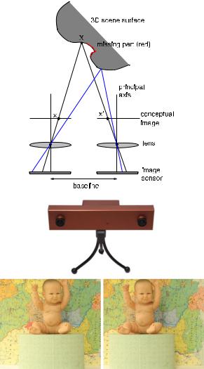
Stereo refers to multiple images taken simultaneously using two or more cameras, which are collectively called a stereo camera. For example, binocular stereo uses two viewpoints, trinocular stereo uses three viewpoints, or alternatively there may be many cameras distributed around the viewing sphere of an object. Stereo derives from the Greek word stereos meaning solid, thus implying a 3D form of visual information. In this chapter, we will use the term stereo vision to imply a binocular stereo system. At the top of Fig. 2.1, we show an outline of such a system.
If we can determine that imaged points in the left and right cameras correspond to the same scene point, then we can determine two directions (3D rays) along which the 3D point must lie. (The camera parameters required to convert the 2D image positions to 3D rays come from a camera calibration procedure.) Then, we can intersect the 3D rays to determine the 3D position of the scene point, in a process
38 |
S. Se and N. Pears |
Fig. 2.1 Top: Plan view of the operation of a simple stereo rig. Here the optical axes of the two cameras are parallel to form a rectilinear rig. However, often the cameras are rotated towards each other (verged) to increase the overlap in their fields of view. Center:
A commercial stereo camera, supplied by Videre Design (figure courtesy of [59]), containing SRI’s Small Vision System [26]. Bottom: Left and right views of a stereo pair (images courtesy of [34])
known as triangulation. A scene point, X, is shown in Fig. 2.1 as the intersection of two rays (colored black) and a nearer point is shown by the intersection of two different rays (colored blue). Note that the difference between left and right image positions, the disparity, is greater for the nearer scene point. Note also that the scene surface colored red cannot be observed by the right camera, in which case no 3D shape measurement can be made. This scene portion is sometimes referred to as a missing part and is the result of self-occlusion. A final point to note is that, although the real image sensor is behind the lens, it is common practice to envisage and use a conceptual image position in front of the lens so that the image is the same orien-