Материал: m013802e_a

Decentral control with controller (3)
The on site controller controls an assigned function area, e.g. a machine unit or components of a transport system. The unit test can be made independently, i.e. without higher ranking controls.
The higher ranking controls transmit data to the controller via the bus system, e.g. the operating mode, set point values or the current production program (recipe). The controller transmits local operating data to the higher ranking controls, such as operating and control messages, actual values, counter readings etc. The complete linking for actuator triggering is made in the controller, in other words directly on site. This permits a fieldbus independent reaction of the controls.
In the case of a fieldbus failure the control program can be independently further processed and the node put into a defined status.
MODBUS / Introduction |
7 |
15.12.99

|
|
|
|
|
|
|
|
|
|
|
|
|
|
|
|
|
|
|
|
|
|
|
|
8 |
MODBUS / Introduction |
||
15.12.99
2 MODBUS Coupler/Controller
2.1 Hardware
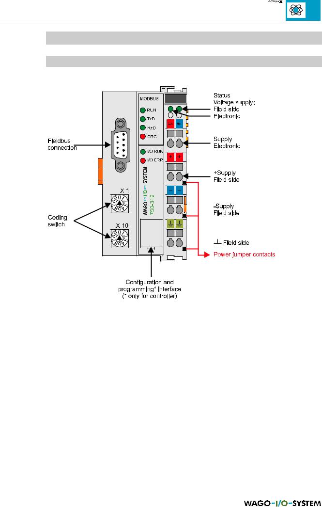
Fig. 2.1: MODBUS coupler/controller
The illustration above applies both to the MODBUS coupler as well as for the MODBUS controller.
Each coupler/controller comprises of two enclosure sections:
left: |
enclosure for the electronics for bus connection and processing |
right: |
a fixed installed power supply module as connection and distribution for the |
|
power supply to the electronics in the coupler/controller enclosure, the |
|
assembled I/O modules and the power supply in the field area. |
MODBUS / Coupler/controller |
9 |
15.12.99
2.2 Power supply
Fig. 2.2: Power supply
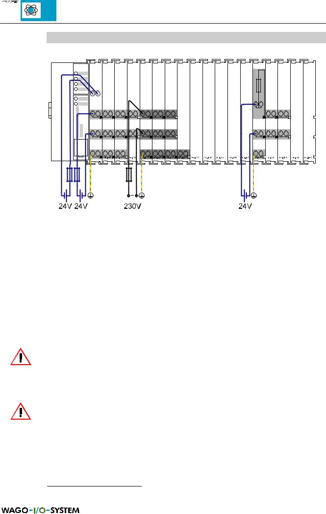
The power supply on the field side is electrically isolated from the electronic supply. In this manner sensors and actuators can be supplied and fused by a separate voltage source.
If a non-regulated power supply is used for the 24 V voltage supply of the coupler/controller electronics, it must be ensured that they are supported by a capacitor (200 µF per 1 A load current). To this effect a back-up capacitor module 1 was developed for the WAGO-I/O SYSTEM. This module serves for smoothing an unstable 24 V DC voltage supply, in as much as the specified voltage deviation required cannot be maintained. Cause for these fluctuations could be a voltage interruption on the primary side, a secondary side overload or the switching of “non quenched” inductivity and capacities.
ATTENTION!
Under no circumstances connect a voltage supply other than 24 V DC on the + and – power supply modules of the coupler/controller. A power supply voltage of max. 230 V AC can only be supplied via the power supply modules 750-609, 750-611 and 750-612!
ATTENTION!
Disconnect the PE lead wires prior to undertaking an insulation test, otherwise this will result in incorrect results or destruction of the I/O module.
1 Back-up capacitor module, Order No. 288-824 |
|
10 |
MODBUS / Coupler/controller |
15.12.99
2.2.1 Electronic supply voltage
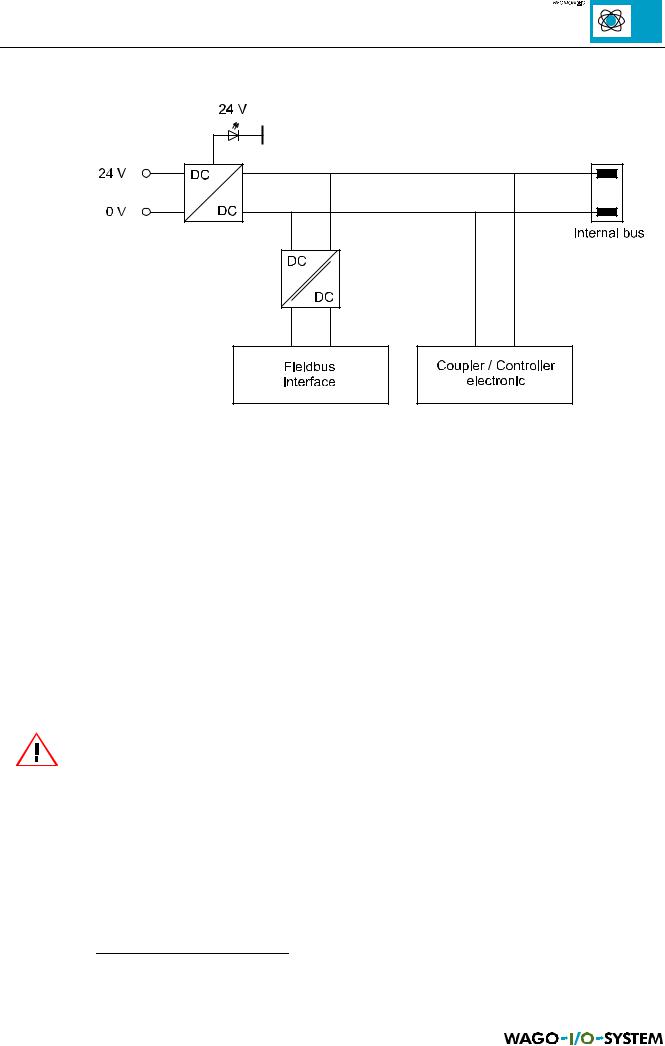
Fig. 2.3: Electronic supply voltage
The electronic supply voltage (24 V DC) is adapted using a voltage regulator and led to the coupler/controller electronics as well as to the internal bus. The electrical isolation of the external fieldbus system is made via a DC/DC converter and via an optocoupler in the fieldbus interface.
The internal bus includes the internal communication between the coupler/controller and the I/O modules as well as the power supply for the I/O modules. The maximum power supply is 1.65 A. If the sum of the internal power consumption of all I/O modules exceeds this value it is necessary to fit additional internal system supply modules2.
The control electronics in the I/O modules are supplied by snap-fit mounting the I/O modules using the internal bus contacts. A reliable contact is assured by gold plated, self cleaning slide contacts. The removal of a I/O module will cause an interruption of the connection to the following I/O modules. The coupler/controller localises the interruption point and sends a corresponding fault message via the red LED ‘I/O ERR’.
ATTENTION!
Removing or inserting the I/O modules with the voltage applied can lead to undefined conditions. For this reason only undertake work on the I/O modules when isolated from the power supply!
2 Internal system supply modules, order No. 750-613
MODBUS / Coupler/controller |
11 |
15.12.99