Материал: m083300e

62 • Fieldbus coupler / controller
Fieldbus coupler 750-333
3.1.9.6Channel based diagnosis
The channel based diagnosis is intended for detailing the identification based diagnosis. A structure is appended to each device status per faulty slot which comprises of a header byte, a byte, the channel type supplying the channel number and a third byte, which describes the fault type and the channel organisation.
Byte |
Information |
|
|
|
|
Meaning |
|||
|
|
|
|
|
|
|
|
|
|
22 |
1 |
0 |
x |
x |
x |
x |
x |
x |
Header channel based diagnosis |
|
|
|
|
|
|
|
|
|
(x: 1 to 63, slots of the module) |
|
|
|
|
|
|
|
|
|
|
23 |
a |
a |
x |
x |
x |
x |
x |
x |
Channel type (a) and |
|
|
|
|
|
|
|
|
|
channel number x: 0 to 3 |
|
0 |
1 |
|
|
|
|
|
|
Input channel |
|
1 |
0 |
|
|
|
|
|
|
Output channel |
|
1 |
1 |
|
|
|
|
|
|
Input / output channel |
|
|
|
|
|
|
|
|
|
|
24 |
t |
t |
t |
x |
x |
x |
x |
x |
Channel type (t) and |
|
|
|
|
|
|
|
|
|
fault type (x) |
|
0 |
0 |
0 |
|
|
|
|
|
No allocation |
|
0 |
0 |
1 |
|
|
|
|
|
1 Bit |
|
0 |
1 |
0 |
|
|
|
|
|
2 Bit |
|
0 |
1 |
1 |
|
|
|
|
|
4 Bit |
|
1 |
0 |
0 |
|
|
|
|
|
1 Byte |
|
1 |
0 |
1 |
|
|
|
|
|
1 Word |
|
1 |
1 |
0 |
|
|
|
|
|
2 Words |
|
|
|
|||||||
25-27 |
Next channel based diagnosis message (as byte 22 – 24) |
||||||||
|
|
||||||||
28-30 |
Next channel based diagnosis message (as byte 22 – 24) |
||||||||
|
|
|
|
|
|
|
|
|
|
... |
... |
|
|
|
|
|
|
|
|
|
|
||||||||
61-63 |
Last displayable channel based diagnosis message (such as byte 22 – 24) |
||||||||
|
|
|
|
|
|
|
|
|
|
D R A F T |
WAGO-I/O-SYSTEM 750 |
2001-02-27 |
PROFIBUS |

Fieldbus coupler / controller |
• 63 |
Fieldbus coupler 750-333 |
|
|
|
3.1.9.6.1Fault types of I/O modules with diagnostic capability
The fault types refer to standardised types.
Fault |
Meaning |
type |
|
0 |
Not specified |
|
|
1 |
Short circuit |
|
|
2 |
Low voltage |
|
|
3 |
High voltage |
|
|
4 |
Overload |
|
|
5 |
Over temperature |
|
|
6 |
Line break |
|
|
7 |
Upper limit value exceeded |
|
|
8 |
Lower limit value exceeded |
|
|
9 |
Fault |
|
|
10 ... 15 |
Reserved |
|
|
16 ... 31 |
Manufacturer specific |
|
|
17 |
Field voltage fault |
|
|
18 |
Fuse fault |
|
|
19 |
Buffer overflow |
|
|
20 |
Check sum fault |
|
|
21 |
Parity fault |
|
|
22 |
Receive Timeout (partner) |
|
|
23 |
Receive Timeout |
|
|
26 |
SSI_IN fault |
|
|
27 |
SSI FRAME fault |
|
|
31 |
I/O module fault |
|
|
WAGO-I/O-SYSTEM 750 |
D R A F T |
PROFIBUS |
2001-02-27 |

64 • Fieldbus coupler / controller
Fieldbus coupler 750-333
3.1.9.6.2I/O modules fault cases
Article number |
Channel |
Fault type |
Meaning |
|
type |
||||
|
|
|
||
750-418, 750-419, |
'001 |
0.1001' |
Fault (line break, overload or short |
|
750-507, 750-522 |
|
|
circuit) |
|
|
|
|
|
|
750-506 |
'001 |
0.0001' |
Short circuit |
|
|
|
0.0010' |
Lower voltage |
|
|
|
0.0110' |
Line break |
|
|
|
0.1001' |
Error |
|
|
|
|
|
|
750-461, 750-469 |
'101 |
0.0110' |
Line break |
|
|
|
0.1000' |
Lower limit value gone below |
|
|
|
1.0000' |
Parameterisation fault |
|
|
|
1.1111' |
I/O module fault |
|
|
|
|
|
|
750-462, 750-465, |
'101 |
0.0111' |
Lower limit value gone below |
|
750-466, 750-472, |
|
0.1000' |
Upper limit value exceeded |
|
750-474, 750-479, |
|
1.0000' |
Parameterisation fault |
|
750-480 |
|
1.1111' |
I/O module fault |
|
|
|
|
|
|
750-610, 750-611, |
'001 |
1.0001' |
Field voltage fault |
|
|
|
1.0010' |
Fuse fault |
|
|
|
|
|
|
750-630 |
'110 |
1.1010' |
SSI_IN fault (external fault) |
|
|
|
1.1011' |
SSI FRAME fault |
|
|
|
1.0000' |
Parameterisation fault |
|
|
|
1.1111' |
I/O module fault |
|
|
|
|
|
|
750-635, 750-637 |
'110 |
0.1001' |
Error |
|
|
|
1.0000' |
Parameterisation fault |
|
|
|
1.1111' |
I/O module fault |
|
|
|
|
|
|
750-650, 750-651, |
'110 |
0.1001' |
Buffer overflow |
|
750-653, 750-654 |
('000) |
1.0000' |
Parameterisation fault |
|
|
|
1.1111' |
I/O module fault |
|
|
|
|
|
D R A F T |
WAGO-I/O-SYSTEM 750 |
2001-02-27 |
PROFIBUS |
Fieldbus coupler / controller |
• 65 |
Fieldbus coupler 750-333 |
|
|
|
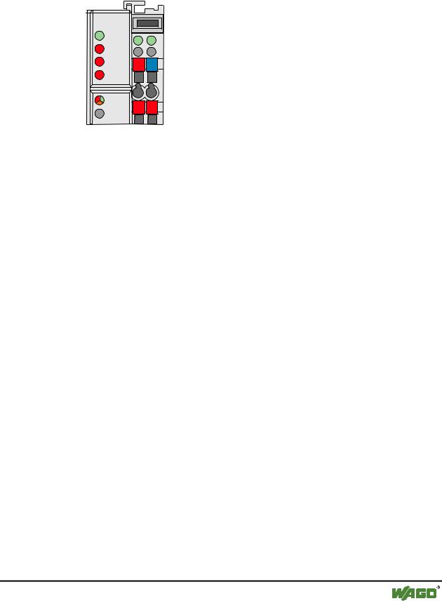
3.1.10LED signalling
The coupler possesses several LED’s for on site signalling of the coupler operating status or the complete node
PROFIBUS |
|
|
|
RUN |
A |
|
|
|
|
|
|
|
|
C |
|
BF |
B |
|
|
|
D |
|
|
|
|
|
|
DIA |
24V |
0V |
|
|
|
||
BUS |
|
|
|
I/O |
+ |
+ |
|
|
|
||
Fig. 3-10: Display elements 750-333 |
g012106x |
||
3.1.10.1Blink code
Detailed fault messages are displayed with the aid of a blink code. A fault is cyclically displayed with up to 3 blink sequences.
•The first blink sequence (approx. 10 Hz) starts the fault display.
•The second blink sequence (approx. 1 Hz) following a pause. The number of blink pulses indicates the fault code.
•The third blink sequence (approx. 1 Hz) follows after a further pause. The number of blink pulses indicates the fault argument.
WAGO-I/O-SYSTEM 750 |
D R A F T |
PROFIBUS |
2001-02-27 |

66 • Fieldbus coupler / controller
Fieldbus coupler 750-333
3.1.10.2Fieldbus status
The upper four LED´s signal the operating conditions of the PROFIBUS communication.
LED |
Colour |
Meaning |
RUN |
green |
The 'RUN' LED indicates to the user if the fieldbus coupler is per- |
|
|
fectly initialised. |
|
|
|
BF |
red |
The 'BF' LED indicates that the communication functions via the |
|
|
PROFIBUS. |
|
|
|
DIA |
red |
The 'DIA' LED indicates an external diagnosis. |
|
|
|
BUS |
red |
The 'BUS' LED signals a projecting fault. |
|
|
|
RUN |
BF |
DIA |
BUS |
Meaning |
off |
off |
off |
off |
No operating voltage to the coupler (status LED of |
|
|
|
|
the bus coupler supply does not light up) or a |
|
|
|
|
hardware fault is present. |
|
|
|
|
|
on |
on |
* |
off |
PROFIBUS interface started, baud rate was not yet |
|
|
|
|
recognised. |
|
|
|
|
|
on |
blinks |
* |
off |
Baud rate recognised, station not yet parameterised |
|
|
|
|
and configured. |
|
|
|
|
|
on |
blinks |
on |
blinks |
Slave was incorrectly projected. |
|
|
|
cycli- |
Fault message via blink code |
|
|
|
cally |
|
|
|
|
|
|
on |
off |
* |
off |
The coupler is exchanging data. |
|
|
|
|
|
on |
* |
on |
* |
The coupler signals an existing diagnosis. |
|
* Not relevant |
|
|
|
D R A F T |
WAGO-I/O-SYSTEM 750 |
2001-02-27 |
PROFIBUS |