Материал: m083300e

Fieldbus coupler / controller |
• 67 |
Fieldbus coupler 750-333 |
|
|
|
3.1.10.3Fault message via blink code of the BUS-LED
Fault argument |
Fault description |
Fault code 1: Fault in parameterisation telegram |
|
1 |
Insufficient parameterisation data |
|
|
2 |
Excessive parameterisation data |
|
|
Fault code 2: Fault in parameterisation telegram |
|
n |
Faulty parameterised byte n |
|
|
Fault code 3: Fault in configuration telegram |
|
1 |
Insufficient configuration data |
|
|
2 |
Excessive configuration data |
|
|
Fault code 4: Fault in configuration telegram |
|
n |
Configuration byte (module) n is faulty |
|
|
Fault code 5: Fault in the data length |
|
1 |
maximum input data length exceeded |
|
|
2 |
maximum output data length exceeded |
|
|
Fault code 6: Compilate buffer overflow |
|
1 |
Compilate buffer overflow for DP process image |
|
|
WAGO-I/O-SYSTEM 750 |
D R A F T |
PROFIBUS |
2001-02-27 |
68 • Fieldbus coupler / controller
Fieldbus coupler 750-333
3.1.10.4Node status
The 'I/O' LED indicates the node operation and signals faults occurring.
I/O |
Meaning |
green |
Data cycle on the internal bus |
|
|
off |
No data cycle on the internal bus |
|
|
red |
Coupler hardware defective |
|
|
red |
When starting: internal bus is initialised |
blinks |
During operation: general internal bus fault |
|
|
red |
Fault message during internal bus reset and internal fault: |
blinks cyclically |
|
|
|
orange |
FLASH access to bus coupler firmware |
|
|
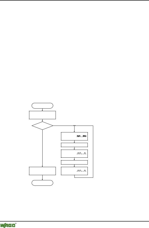
The coupler starts after switching on the supply voltage. The "I/O" LED flashes red. Following a fault free run up the "I/O" LED changes to green steady light.
In the case of a fault the "I/O" LED continues blinking red. The fault is cyclically displayed with the blink code.
Versorgungsspannung
einschalten
Koppler-Hochlauf
“I/O”-LED blinkt
Fehler |
Ja |
|
|
Nein |
|
“I/O”-LED
1. Blinksequenz
(leitet opt. Anzeige eines Fehlers ein)
1. Pause
“I/O”-LED
2. Blinksequenz
Fehlercode (Anzahl Blinkimpulse)
2. Pause
“I/O”-LED
“I/O”-LED an 3. Blinksequenz
Fehlerargument (Anz. Blinkimp.)
Feldbusstart |
|
Fig. 3-11: Signalling the LED's node status |
g012111d |
After overcoming a fault restart the coupler by switching off and on the supply voltage.
D R A F T |
WAGO-I/O-SYSTEM 750 |
2001-02-27 |
PROFIBUS |
Fieldbus coupler / controller |
• 69 |
Fieldbus coupler 750-333 |
|
|
|
3.1.10.5Fault message via the blink code of the I/O LED
Fault argument |
Fault description |
Fault code 1: Hardware and configuration fault |
|
0 |
EEPROM check sum fault / check sum fault in parameter area of the |
|
flash memory |
|
|
1 |
Overflow of the internal buffer memory for the inline code |
|
|
2 |
Unknown data type |
|
|
3 |
Module type of the flash program memory could not be determined / |
|
is incorrect |
|
|
4 |
Fault during writing in the flash memory |
|
|
5 |
Fault when deleting the FLASH memory |
|
|
6 |
Changed I/O module configuration found after AUTORESET |
|
|
7 |
Fault when writing in the serial EEPROM |
|
|
8 |
Invalid firmware |
|
|
Fault code 2: Fault in programmed configuration |
|
0 |
Incorrect table entry |
|
|
Fault code 3: Internal bus command fault |
|
0 |
I/O module(s) has (have) identified internal bus command as incor- |
|
rect |
|
|
Fault code 4: Internal bus data fault |
|
0 |
Data fault on internal bus or |
|
Internal bus interruption on coupler |
|
|
n* (n>0) |
Internal bus interrupted after I/O module n |
|
|
Fault code 5: Register communication fault |
|
n* |
Internal bus fault during register communication with the I/O module |
|
n |
|
|
Fault code 7: I/O module not supported |
|
n* |
I/O module not supported at position n |
* The number of blink pulses (n) indicates the position of the I/O module. I/O modules without data are not counted (e.g. supply module without diagnosis)
Example: the 13th I/O module is removed.
1.The "I/O" LED generates a fault display with the first blink sequence (approx. 10 Hz).
2.The first pause is followed by the second blink sequence (approx. 1 Hz). The "I/O" LED blinks four times and thus signals the fault code 4 (internal bus data fault).
3.The third blink sequence follows the second pause. The "I/O ERR" LED blinks twelve times. The fault argument 12 means that the internal bus is interrupted after the 12th I/O module.
WAGO-I/O-SYSTEM 750 |
D R A F T |
PROFIBUS |
2001-02-27 |

70 • Fieldbus coupler / controller
Fieldbus coupler 750-333
3.1.10.6Supply voltage status
LED |
Colour |
Meaning |
A |
green |
Status of the operating voltage – system |
|
|
|
C |
green |
Status of the operating voltage – power jumper contacts |
|
|
|
There are two green LED’s in the coupler supply section to display the supply voltage. The left LED (A) indicates the 24 V supply for the coupler. The right hand LED (C) signals the supply to the field side, i.e. the power jumper contacts.
D R A F T |
WAGO-I/O-SYSTEM 750 |
2001-02-27 |
PROFIBUS |

Fieldbus coupler / controller |
• 71 |
Fieldbus coupler 750-333 |
|
|
|
3.1.11Fault behaviour
3.1.11.1Fieldbus failure
A fieldbus failure has occurred when the master is switched off or the bus cable is interrupted. A fault in the master can also lead to a fieldbus failure.
The red "BF" LED lights up.
The failure of the fieldbus can activate the parameterisable substitute value of the I/O modules. During projecting of the inputs and outputs a substitute value can be laid down for each channel.
Substitute value |
Value (bit orientated) |
Value (byte orientated) |
strategy |
Digital output modules |
Analog output modules |
Minimum value |
0 |
0 or 4 mA, 0 V |
|
|
|
Maximum value |
1 |
20 mA, 10 V |
|
|
|
Substitute value |
0 or 1 |
0/4 ... 20 mA, -10 ... +10 V |
|
|
|
Stop internal bus |
Behaviour determined by I/O module |
|
|
|
|
The value is entered in the output process image by the coupler. With I/O modules with byte orientated data width, e.g. the pulse width module, the substitute value is determined via the value area.
As soon as the fieldbus is active the process data is transmitted and the output correspondingly set in the nodes.
WAGO-I/O-SYSTEM 750 |
D R A F T |
PROFIBUS |
2001-02-27 |