Материал: m083300e
WAGO-I/O-SYSTEM 750 • 7
System Description
2.1.3I/O Modules (2)
In the I/O modules, the incoming process data is converted. Corresponding to the different requirements, special I/O modules are available for a variety of functions. There are digital and analog inputs and outputs and modules for special functions (Counter modules, Terminal blocks for encoder and resolvers and communication modules).
2.1.4End Module (3)
A End Module is needed for faultless operation of the node. The termination module is always placed as the last module in order to obtain a termination of the fieldbus node. This module has no I/O function.
WAGO-I/O-SYSTEM 750 |
D R A F T |
PROFIBUS |
2001-02-27 |
8• WAGO-I/O-SYSTEM 750
Installation
2.2 Installation
2.2.1Safty notes
ESD (Electrostatic Discharge)
The modules are equipped with electronic components which may be destroyed by electrostatic discharge.When handling the modules, ensure that the environment (persons, workplace and packing) is well grounded. Avoid touching conductive components, e.g. gold contacts.
Attention
Switch off the system prior to working on bus modules!
2.2.2Mechanical Installation
All system components can be snapped directly on a carrier rail in accordance with the European standard EN 50022 (DIN 35).
Attention
Ensure that the carrier rail is fastened with countersunk head screws or blind rivets as the snap-on foot of the I/O components extends onto the carrier rail.
The installation is simple and space saving. All modules have the same shape to minimize the project commitment.
The reliable positioning and connection of the coupler and the individual I/O modules is made using a tongue and groove system. Due to the automatic locking, the individual components are securely seated on the rail after installing.
D R A F T |
WAGO-I/O-SYSTEM 750 |
2001-02-27 |
PROFIBUS |
WAGO-I/O-SYSTEM 750 • 9
Installation
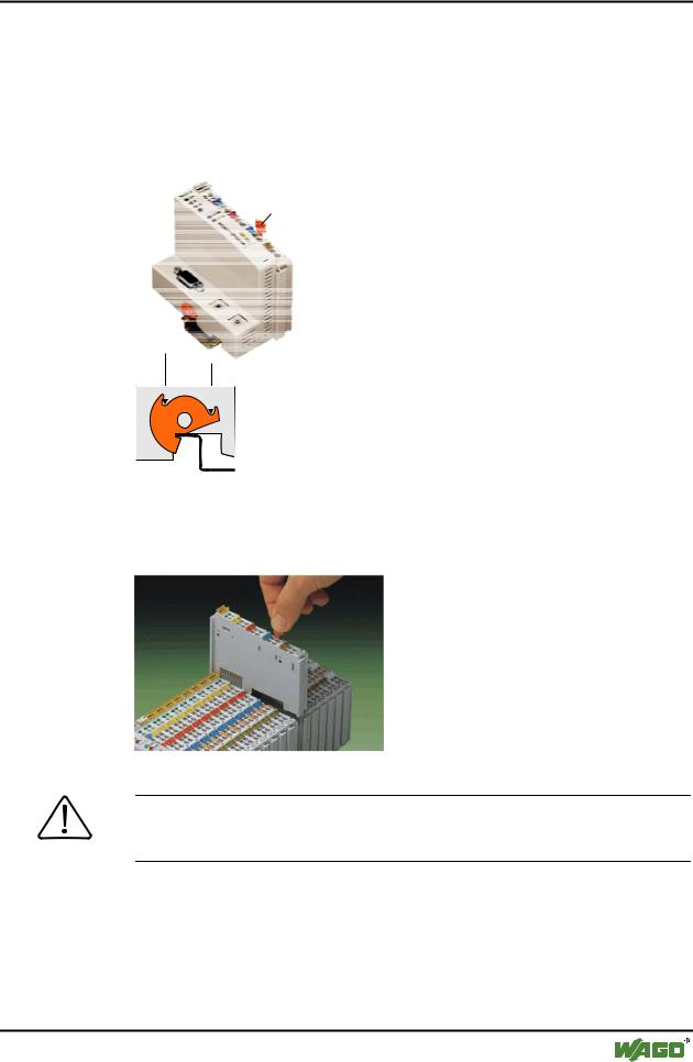
To secure the coupler/controller against moving sideways, fix it with the orange colored locking disc on the carrier rail. To fix, insert a screwdriver into the top groove of the locking disc and press.
To pull out the fieldbus coupler, release the locking disc by pressing on the bottom groove with a screwdriver and then pulling the orange colored unlocking lug.
Entriegelungs-
lasche
fixieren
lösen
Fig. 2-2: Coupler/Controller and unlocking lug |
g012201d |
It is also possible to release an individual I/O module from the unit by pulling an unlocking lug.
Fig. 2-3: Releasing a I/O Module |
p0xxx01x |
Danger
Ensure that an interruption of the PE will not result in a condition which could endanger a person or equipment!
WAGO-I/O-SYSTEM 750 |
D R A F T |
PROFIBUS |
2001-02-27 |
10• WAGO-I/O-SYSTEM 750
Installation
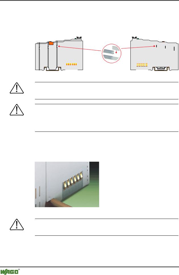
Self-cleaning power jumper contacts conduct the supply voltage for the field side. They are located on either side of the modules. The female contacts on the right-hand side of the fieldbus coupler and the bus modules are designed as spring contacts to protect against accidental contact. Male contacts are located on the left-hand side of the bus modules.
Pos. 1
Pos. 2
|
|
|
|
|
|
|
|
|
|
|
|
|
|
|
|
|
|
|
|
|
|
|
|
|
|
|
|
|
|
|
|
|
|
|
|
|
|
|
|
Fig. 2-4: Power Jumper Contacts |
|
|
|
|
|
|
|
g01xx00d |
|
Danger
The power contacts are sharp-edged. Handle the module carefully to prevent injury.
Attention
Please take into consideration that some bus modules have no or only some power jumper contacts. The design of some modules does not physically allow assembly them in rows as the grooves for the male contacts are closed at the top.
The data contacts are designed as self-cleaning gold spring contacts which automatically produce a secure connection.
Fig. 2-5: Data contacts |
p0xxx07x |
Warning
Do not connect the I/O module to gold spring contacts in order to avoid soiling or scratches!
D R A F T |
WAGO-I/O-SYSTEM 750 |
2001-02-27 |
PROFIBUS |
WAGO-I/O-SYSTEM 750 • 11
Electrical Installation
2.3 Electrical Installation
2.3.1Wire Connection
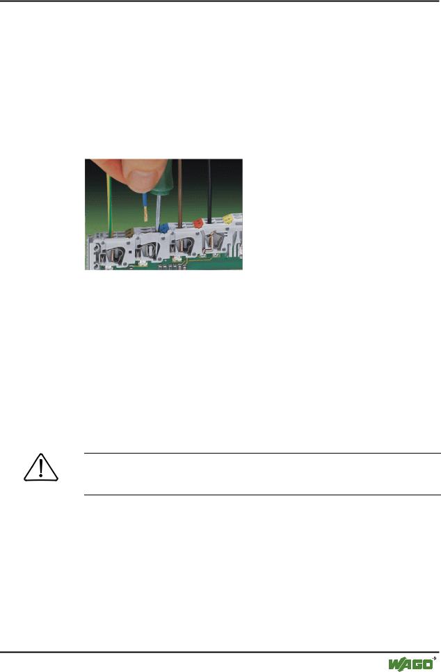
Conductors with a cross section of 0.08 to 2.5 mm² (AWG 28-12) can be connected using a CAGE CLAMP connection to achieve a vibration resistant, fast and maintenance free connection. To actuate CAGE CLAMP enter an actuation tool in the opening above the connection. Following this, enter the conductor in the corresponding opening. The conductor is clamped securely with the removal of the actuation tool.
Fig. 2-6: Inserting conductor end |
p0xxx06x |
The clamping force adjusts automatically to the cross section. The full surface of the CAGE CLAMP pressure is applied against the conductor without damaging it. Conductor deformation is compensated for and self-loosening is avoided. The transition point between the conductor and the CAGE CLAMP is protected against corrosive influences. The connection can be made quickly and is also maintenance free, saving the costs for a periodic checking of terminal connections.
Two carrier rail contacts responsible for the electrical contact between the grounded carrier rail and the controller, are fitted underneath the coupler/controller.
Attention
Ensure a perfect contact point between carrier rail contacts and carrier rail. The carrier rail must be grounded.
WAGO-I/O-SYSTEM 750 |
D R A F T |
PROFIBUS |
2001-02-27 |