Материал: m083300e
12• WAGO-I/O-SYSTEM 750
Electrical Installation
2.3.2Change fuse
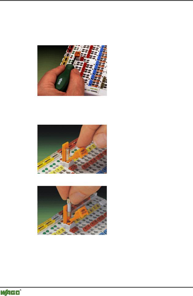
Some Power supply modules of the WAGO-I/O-SYSTEM 750 are equipped with a fuse holder. To isolate the modules to the right of the power supply, the fuse can be removed from the fuse holder. For this insert a srew driver into one of the slits available on each side and lift the holder
Fig. 2-7: Removing the fuse holder |
p0xxx05x |
The fuses can be removed from or inserted into the holder with the fuse holder cover and push the fuse holder pushed back into the original position.
Fig. 2-8: Opening the fuse holder |
p0xxx03x |
Fig. 2-9: Change fuse |
p0xxx04x |
D R A F T |
WAGO-I/O-SYSTEM 750 |
2001-02-27 |
PROFIBUS |
WAGO-I/O-SYSTEM 750 • 13
Power supply
2.4 Power supply
1 |
|
|
750-400 |
750-410 |
750-403 |
2
-612 |
750-512 |
750-512 |
750-513 |
750-616 |
750-454 |
750-467 |
750-461 |
750-550 |
-610 |
750-552 |
750-630 |
750-650 |
750-600 |
|
~ |
|
24V 24V |
230V |
24V |
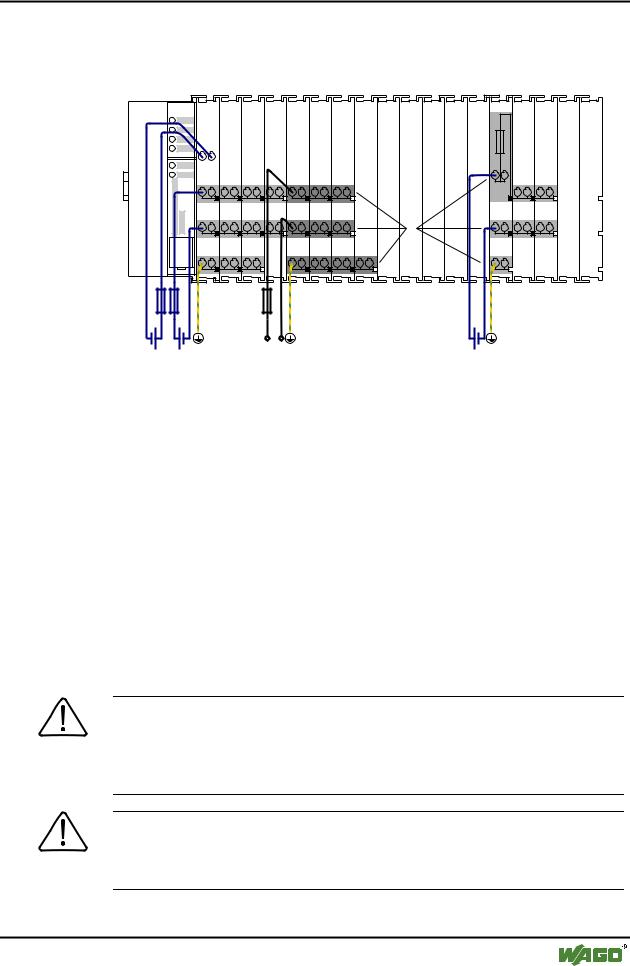
Fig. 2-10: Power supply |
|
g01xx02x |
1 – Power supply System
2 – Power supply Field-side
The power supply on the field side is electrically isolated from the system supply. In this manner sensors and actuators can be supplied and fused by a separate voltage source.
If a non-regulated power supply is used for the coupler/controller electronics 24 V voltage supply , it must be filtered through a capacitor (200 µF per 1 A load current). To this effect a back-up capacitor module (Order-No. 288-824) was developed for the WAGO-I/O-SYSTEM. This module serves to regulate a noisy 24 V DC voltage supply, to keep the ripple voltage within specified limits. The cause for these fluctuations could be a voltage interruption on the primary side, a secondary side overload or the switching of ”non quenched“ inductance or capacitance.
Warning
The supply modules + and – which are permanently integrated on the buscouplers, can be supplied with 24 V DC only.
120 V AC and 230 V AC can only be supplied via modules 750-609, 750-611 and 750-612!
Warning
The ground (earth) field side contact should be disconnected when testing the isolation. Otherwise the results could be wrong or the module could be destroyed.
WAGO-I/O-SYSTEM 750 |
D R A F T |
PROFIBUS |
2001-02-27 |
14• WAGO-I/O-SYSTEM 750
Power supply
2.4.1System supply voltage
The system supply voltage (24 V DC) is filtered with a voltage regulator before powering the coupler electronics as well as to the internal bus. Electrical isolation from the external fieldbus system depends on the type of Coupler/Controller.
The internal bus includes the internal communication between the coupler/controller and the bus modules as well as the power supply for the bus modules. The power supply is limited to a maximum value. This value depends on the type of Coupler/Controller. If the sum of the internal power consumption of all bus modules exceeds this value, it is necessary to add additional internal system supply modules (Order-No. 750-613).
The control electronics in the bus modules are powered by snap-fit mounting the bus modules using the internal bus contacts. A reliable contact is assured by the gold plated, self cleaning slide contacts. The removal of a bus module will cause an interruption in communication to the following bus modules.
The coupler/controller identifies the interruption point and displays a corresponding fault message.
Warning
Removing or inserting the I/O modules with the voltage applied can lead to undefined conditions. For this reason only undertake work on the I/O modules when isolated from the power supply!
D R A F T |
WAGO-I/O-SYSTEM 750 |
2001-02-27 |
PROFIBUS |
WAGO-I/O-SYSTEM 750 • 15
Power supply
2.4.2Supply Voltage Field Side
The voltage is automatically supplied when the I/O modules are snapped together. Self-cleaning power jumper contacts (P.J.C.s) ensure safe connections. The current capacity of the power contacts is 10 A max.
The PE contact is a preceding ground (earth) contact corresponding to the standards which can be used as a protective earth. The contact has a leakage capacity of 125 A.
Warning
Produce a low impedance connection from the carrier rail to the PE contact point in the switch cabinet.
Attention
Depending on the I/O function, some modules do not have P.J.C.s. It is important to note this when assembling a node. Many modules require field side power, many do not. Please review the circuit diagrams of the individual modules. An additional power supply module may be necessary.
Refer to the individual terminal/module data sheets!
When adding a power supply module, the field supply is always interrupted at the power contacts. From this point a new power supply is made, which can also include a potential change. This feature guarantees a high degree of system flexibility.
WAGO-I/O-SYSTEM 750 |
D R A F T |
PROFIBUS |
2001-02-27 |
16• WAGO-I/O-SYSTEM 750
Manufacturing Number
2.5 Manufacturing Number
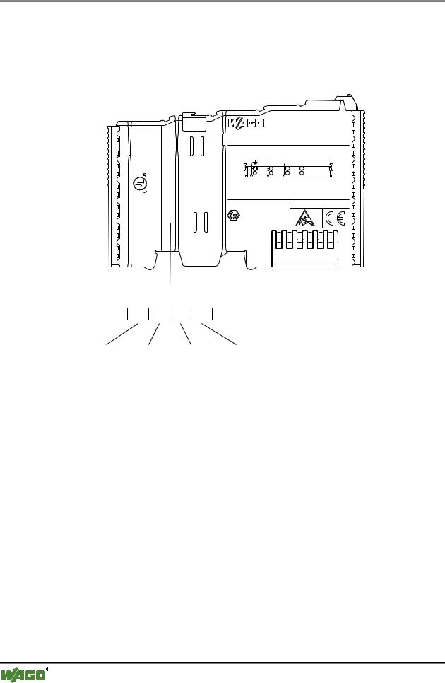
The production number is part of the lateral marking on the component. The number contains the production date, the software version and the hardware of the component.
24V DC AWG 28-14 55°C max ambient
CL I DIV Grp. A B C D op temp code T4A
LISTED 22ZA AND 22XM
-02----03 |
4246 |
1- |
2 |
090 |
|
|
ITEM-NO.:750-400 |
Hansastr. 27 |
2DI 24V DC 3.0ms |
|
|
D-32423 Minden |
0.08-2.5mm2 |
0V 24V DI1
Di2
PATENTS PENDING
II 3 G
KEMA 01ATEX1024 X EEx nA II T4
Manufacturing Number |
|
|||
|
0 9 0 |
1 - - 0 |
2 |
|
Calendar |
Year |
Software |
Hardware |
|
week |
|
version |
version |
|
Fig. 2-11: |
Manufacturing Number |
g01xx09e |
||
The remaining digits and characters represent internal information by WAGO Kontakttechnik GmbH.
As of calendar week 09/2001, the production number is additionally printed on the cover of the configuration and programming interface of the fieldbus coupler or controller.
D R A F T |
WAGO-I/O-SYSTEM 750 |
2001-02-27 |
PROFIBUS |