Материал: part17
Page 66 |
DICOM PS3.17 2020a - Explanatory Information |
ModalityWorklistManagementSOPClassenablesamodalityoperatortorequesttheschedulinginformationfortheorderedprocedures. Aworklistcanbeconstructedbasedontheschedulinginformation.ThehandlingoftherequestedimagingprocedureinDICOMStudy Management and in DICOM Worklist Management are closely related. The worklist also conveys patient/study demographic inform- ation that can be incorporated into the images.
Worklist Management is completed once the imaging procedure has started and the Scheduled Procedure Step has been removed from the Worklist, possibly in response to the Modality Performed Procedure Step (B). However, Study Management continues throughout all stages of the Study, including interpretation. The actual procedure performed (based on the request) and information about the images produced are conveyed by the DICOM Study Component SOP Class or the Modality Performed Procedure Step SOP Classes.
|
|
Modality Worklist |
|
|
|
|
Real World Model |
|
|
|
|
|
Extension |
|
Original DICOM |
|
|
|
|
Real World Model |
|
Patient |
|
|
|
|
|
|
|
1 |
1 |
|
1 |
1 |
has |
makes |
|
has |
has |
1-n |
0-n |
|
0-n |
0-n |
|
Visit |
|
Service Episode |
Imaging |
|
|
Service Request |
||
|
|
|
|
|
0-n |
0-n |
|
0-n |
1 |
includes |
includes |
occurs during |
is context for |
has |
|
|
|
1 |
1-n |
1 |
|
1 |
|
|
Study |
|
Requested Procedure |
|
|
|
1-n |
|
|
|
to be |
|
comprised of |
|
specifies |
is comprised of |
performed according |
|
1-n |
|
|
|
to |
|
|
|
|
|
|
Modality performed |
1-n |
1-n |
Scheduled |
Procedure |
|
|
B |
||||
Procedure Steps |
|
Procedure Step |
Plan |
||
|
Result |
|
Procedure |
|
|
|
|
Type |
includes |
specifies |
|
|
|
|
|||
|
|
|
|
||
includes |
includes |
|
|
Action |
|
|
|
Item |
|||
|
|
|
|
|
|
Report |
Amendment |
|
|
|
|
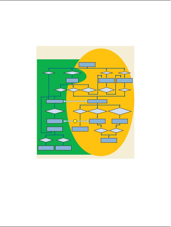
Figure B-2. Relationship of the Original Model and the Extensions for Modality Worklist and Modality Performed Procedure Step Management
FigureB-2showstherelationshipbetweentheoriginalDICOMReal-WorldmodelandtheextensionsofthisReal-Worldmodelrequired to support the Modality Worklist and the Modality Performed Procedure Step. The new parts of the model add entities that are needed to request, schedule, and describe the performance of imaging procedures, concepts that were not supported in the original model. The entities required for representing the Worklist form a natural extension of the original DICOM Real-World model.
Common to both the original model and the extended model is the Patient entity. The Service Episode is an administrative concept that has been shown in the extended model in order to pave the way for future adaptation to a common model supported by other standardizationgroupsincludingHL7,CENTC251WG3,CAP-IEC,etc.TheVisitisintheoriginalmodelbutnotshownintheextended model because it is a part of the Service Episode.
There is a 1 to 1 relationship between a Requested Procedure and the DICOM Study (A). A DICOM Study is the result of a single Requested Procedure. A Requested Procedure can result in only one Study.
- Standard -

DICOM PS3.17 2020a - Explanatory Information |
Page 67 |
A n:m relationship exists between a Scheduled Procedure Step and a Modality Performed Procedure Step (B). The concept of a Modality Performed Procedure Step is a superset of the Study Component concept contained in the original DICOM model. The Modality Performed Procedure Step SOP Classes provide a means to relate Modality Performed Procedure Steps to Scheduled Procedure Steps.
- Standard -

Page 68 |
DICOM PS3.17 2020a - Explanatory Information |
- Standard -

DICOM PS3.17 2020a - Explanatory Information |
Page 69 |
C Waveforms (Informative)
This Annex was formerly located in Annex J “Waveforms (Informative)” in PS3.3 in the 2003 and earlier revisions of the Standard.
C.1 Domain of Application
Waveform acquisition is part of both the medical imaging environment and the general clinical environment. Because of its broad use, there has been significant previous and complementary work in waveform standardization of which the following are particularly im- portant:
ASTM E31.16 - E1467 |
Specification for Transferring Digital Neurophysiological Data Between Independent Computer |
|
|
|
Systems |
CEN TC251 PT5-007 |
- |
Standard Communications Protocol for Computer-Assisted Electrocardiography (SCP-ECG). |
prENV1064 draft |
|
Vital Signs Information Representation Standard (VITAL) |
CEN TC251 PT5-021 |
- draft |
|
HL7 Automated Data SIG |
HL7 Version 2.3, Chapter 7.14-20 |
|
IEEE P1073 - draft |
|
Medical Information Bus Standard (MIB) |
DICOM Section A.10 in PS3.3 |
Standalone Curve Information Object Definition |
|
For DICOM, the domain of waveform standardization is waveform acquisition within the imaging context. It is specifically meant to address waveform acquisitions that will be analyzed with other data that is transferred and managed using the DICOM protocol. It allows the addition of waveform data to that context with minimal incremental cost. Further, it leverages the DICOM persistent object capabilityformaintainingreferentialrelationshipstootherdatacollectedinamulti-modalityenvironment,includingreferencesnecessary for multi-modality synchronization.
Waveform interchange in other clinical contexts may use different protocols more appropriate to those domains. In particular, HL7 may be used for transfer of waveform observations to general clinical information systems, and MIB may be used for real-time physiological monitoring and therapy.
The waveform information object definition in DICOM has been specifically harmonized at the semantic level with the HL7 waveform message format. The use of a common object model allows straightforward transcoding and interoperation between systems that useDICOMforwaveforminterchangeandthosethatuseHL7,andmaybeviewedasanexampleofcommonsemanticsimplemented in the differing syntaxes of two messaging systems.
Note
HL7 allows transport of DICOM SOP Instances (information objects) encapsulated within HL7 messages. Since the DICOM and HL7 waveform semantics are harmonized, DICOM Waveform SOP Instances need not be transported as encapsulated data, as they can be transcoded to native HL7 Waveform Observation format.
C.2 Use Cases
The following are specific use case examples for waveforms in the imaging environment.
•Case 1: Catheterization Laboratory - During a cardiac catheterization, several independent pieces of data acquisition equipment maybebroughttogetherfortheexam.AnelectrocardiographicsubsystemrecordssurfaceECGwaveforms;anX-rayangiographic subsystemrecordsmotionimages;ahemodynamicsubsystemrecordsintracardiacpressuresfromasensoronthecatheter.These subsystems send their acquired data by network to a repository. These data are assembled at an analytic workstation by retrieving from the repository. For a left ventriculographic procedure, the ECG is used by the physician to determine the time of maximum and minimum ventricular fill, and when coordinated with the angiographic images, an accurate estimate of the ejection fraction can be calculated. For a valvuloplasty procedure, the hemodynamic waveforms are used to calculate the pre-intervention and post-in- tervention pressure gradients.
•Case 2: Electrophysiology Laboratory - An electrophysiological exam will capture waveforms from multiple sensors on a catheter; the placement of the catheter in the heart is captured on an angiographic image. At an analytic workstation, the exact location of the sensors can thus be aligned with a model of the heart, and the relative timing of the arrival of the electrophysiological waves at different cardiac locations can be mapped.
- Standard -
Page 70 |
DICOM PS3.17 2020a - Explanatory Information |
•Case3:StressExam-AstressexammayinvolvetheacquisitionofbothECGwaveformsandechocardiographicultrasoundimages from portable equipment at different stages of the test. The waveforms and the echocardiograms are output on an interchange disk, which is then input and read at a review station. The physician analyzes both types of data to make a diagnosis of cardiac health.
C.3 Time Synchronization Frame of Reference
Synchronization of acquisition across multiple modalities in a single study (e.g., angiography and electrocardiography) requires either asharedtrigger,orasharedclock.ASynchronizationModulewithintheFrameofReferenceInformationEntityspecifiesthesynchron- ization mechanism. A common temporal environment used by multiple equipment is identified by a shared Synchronization Frame of Reference UID. How this UID is determined and distributed to the participating equipment is outside the scope of the Standard.
The method used for time synchronization of equipment clocks is implementation or site specific, and therefore outside the scope of this proposal. If required, standard time distribution protocols are available (e.g., NTP, IRIG, GPS).
An informative description of time distribution methods can be found at: http://www.bancomm.com/cntpApp.htm
A second method of synchronizing acquisitions is to utilize a common reference channel (temporal fiducial), which is recorded in the data acquired from the several equipment units participating in a study, and/or that is used to trigger synchronized data acquisitions. Forinstance,the"X-rayon"pulsetrainthattriggerstheacquisitionofframesforanX-rayangiographicSOPInstancecanberecorded as a waveform channel in a simultaneously acquired hemodynamic waveform SOP Instance, and can be used to align the different object instances. Associated with this Supplement are proposed coded entry channel identifiers to specifically support this synchron- ization mechanism (DICOM Terminology Mapping Resource Context Group ID 3090).
C.4 Waveform Acquisition Model
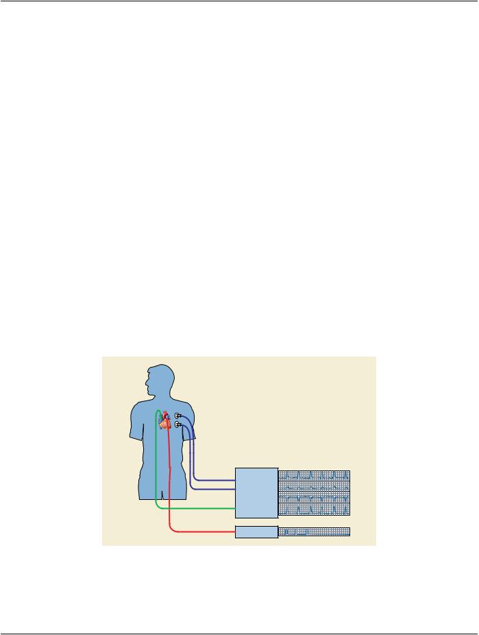
Figure C.4-1 shows a canonical model of waveform data acquisition. A patient is the subject of the study. There may be several sensors placed at different locations on or in the patient, and waveforms are measurements of some physical quality (metric) by those sensors (e.g., electrical voltage, pressure, gas concentration, or sound). The sensor is typically connected to an amplifier and filter, and its output is sampled at constant time intervals and digitized. In most cases, several signal channels are acquired synchronously. The measured signal usually originates in the anatomy of the patient, but an important special case is a signal that originates in the equipment, either as a stimulus, such as a cardiac pacing signal, as a therapy, such as a radio frequency signal used for ablation, or as a synchronization signal.
Sensors / transducers:
•Electrical
•Pressure
•Gas concentration
•Sound
•RF electromagnetic
Amplifier / Filter
Analog-to-Digital
Converter
Waveform
Display
Processor
Stimulator
Figure C.4-1. Waveform Acquisition Model
- Standard -