Материал: part17

Внимание! Если размещение файла нарушает Ваши авторские права, то обязательно сообщите нам

Page 736​

DICOM PS3.17 2020a - Explanatory Information​


Name​


Tag​

Value​

Comment​

>>Code Sequence Macro Values​


(0008,0102)​

(389080008, SCT, "White​CID 7710​


(0008,0100)​

matter of brain and spinal​


cord")​


(0008,0104)​


>>Modifier Code Sequence​


(0040,A195)​


Item 1​


>>>Code Sequence Macro Values​

…​

(24028007, SCT, "Right")​CID 244​

>Track Sequence​


(0066,0102)​


Item 1 (Single Track "C")​


>>Point Coordinates Data​

(0066,0016)​

6, 0.1, 0​

Coordinates of​


5.8, -2, 0​

C1, C2, C3​


6.2, -4.5, 0​


>Recommended Display CIELab Value​

(0062,000D)​

34751/53214/49924/​

Color of C1, C2,​


C3​

>Diffusion Acquisition Code Sequence​

(0066,0133)​


>>Code Sequence Macro Values​


…​

(113223, DCM, "DTI")​

CID 7260​

>Diffusion Model Code Sequence​


(0066,0134)​


>>Code Sequence Macro Values​


…​

(113231, DCM, "Single​

CID 7261​


Tensor")​


>Tracking Algorithm Identification Sequence​

(0066,0104)​


Item 1​


>>Algorithm Family Code Sequence​

(0066,002F)​


>>>Code Sequence Macro Values​

…​

(113211, DCM,​

CID 7262​


"Deterministic")​


>>Algorithm Name​


(0066,0036)​

Example​


>>Algorithm Version​


(0066,0031)​

1.0​


Referenced Instance Sequence​


(0008,114A)​


Item 1​


>Referenced SOP Class UID​


…​

1.2.840.10008.5.1.4.1.1.4​MR Image​


Storage​

>Referenced SOP Instance UID​


…​

1.2.3.4.1​


Item 2​


>Referenced SOP Class UID​


…​

1.2.840.10008.5.1.4.1.1.4​MR Image​


Storage​

>Referenced SOP Instance UID​


…​

1.2.3.4.2​


…​


Item n​


>Referenced SOP Class UID​


…​

1.2.840.10008.5.1.4.1.1.4​MR Image​


Storage​

>Referenced SOP Instance UID​


…​

1.5.6.1​


- Standard -​

DICOM PS3.17 2020a - Explanatory Information​

Page 737​

XXX Volumetric Presentation States​ (Informative)​

XXX.1 Scope of Volumetric Presentation States​

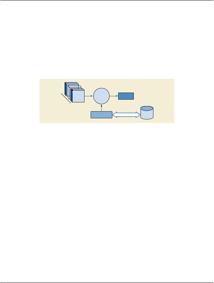
Volume data may be presented through a variety of display algorithms, such as frame-by-frame viewing, multi-planar reconstruction,​ surface rendering and volume rendering. The Volumetric Source Information consists of one or more volumes (3D or 4D) used to​ form the presentation. When a volume Presentation View is created through the use of a Display Algorithm, it typically requires a set​ of Display Parameters that determine the specific presentation to be obtained from the volume data. Persistent storage of the Display​ ParametersusedbyaDisplayAlgorithmtoobtainapresentationfromasetofvolume-relateddataiscalledaVolumetricPresentation​ State (VPS):​

Volumetric

Display

Presentation


Source


Algorithm

(View)


Information


Display Parameters

Presentation State

Persistent


Storage


Figure XXX.1-1. Scope of Volumetric Presentation States​

Each Volumetric Presentation State describes a single view with optional animation parameters. A Volumetric Presentation State​ may also indicate that a particular view is intended to be displayed alongside the views from other Volumetric Presentation States.​ However, descriptions of how multiple views should be presented are not part of a Volumetric Presentation State and should be​ specified by a Structured Display, a Hanging Protocol or by another means.​

TheresultofapplicationofaVolumetricPresentationStateisnotexpectedtobeexactlyreproducibleondifferentsystems.Itisdifficult​ to describe the rendering algorithms in enough detail in an interoperable manner, such that a presentation produced at a later time​ is indistinguishable from that of the original presentation. While Volumetric Presentation States use established DICOM concepts of​ grayscaleandcolormatching(GSDFandICCcolorprofiles)andprovidesagenericdescriptionofthedifferenttypesofdisplayalgorithms​ possible, variations in algorithm implementations within display devices are inevitable and an exact match of volume presentation on​ multiple devices cannot be guaranteed. Nevertheless, reasonable consistency is provided by specification of inputs, geometric de-​ scriptions of spatial views, type of processing to be used, color mapping and blending, input fusion, and many generic rendering​ parameters, producing what is expected to be a clinically acceptable result.​

XXX.1.1 Volumetric Presentation States vs. Softcopy Presentation States​

A Volumetric Presentation State is different from Softcopy Presentation States in several ways:​

1.​Unlike Softcopy Presentation States, a Volumetric Presentation State describes the process of creating a new image rather than​ parameters for displaying an existing one​

2.​Volumetric Presentation State may not be displayed exactly the same way by all display systems due to differences in the imple-​ mentations of rendering algorithms.​

XXX.1.2 Image Creation Process​

While both Volumetric Presentation States and Softcopy Presentation States reference source images, a display application applying​ a Volumetric Presentation State will not directly display the source images. Instead, it will use the source data to construct a volume​ and then create a new view of the volume data to be displayed. Depending on the specific Volumetric Presentation State parameters,​ it is possible that some portion of the inputs may not contribute to the generated view.​

- Standard -​

Page 738​

DICOM PS3.17 2020a - Explanatory Information​

XXX.1.3 Volumetric Presentation State Display Consistency​

Some types of volumetric views may be significantly influenced by the hardware and software used to create them, and the industry​ has not yet standardized the volume rendering pipelines to any great extent.​

Whilevolumegeometryisconsistent,otherdisplaycharacteristicssuchascolor,tissueopacityandlightingmayvaryslightlybetween​ display systems.​

The use of the Rendered Image Reference Sequence (0070,1104) to associate the Volumetric Presentation State with a static ren-​ dering of the same view is encouraged to facilitate the assessment of the view consistency (see Section XXX.2.3).​

XXX.2 Volumetric Presentation States vs. Static Derived Images​

A Volumetric Presentation State creator is likely to be capable of also creating a derived static image (such as a secondary capture​ image)representingthesameview.Dependingontheusecase,eitheraVolumetricPresentationStateoraSecondaryCaptureimage​ or both may be preferred.​

XXX.2.1 Static Derived Images​

Static derived images are intended for direct viewing, and have the following advantages:​

•​supported by a wide variety of viewers​

•​minimal display consistency issues - particularly when paired with a Softcopy Display Presentation State​

•​no volumetric processing is required​

and the following disadvantages​

•​cannot be used to re-create the view from the volume data and then interactively manipulate the view​

•​dynamic views may require the creation of a large number of individual instances​

XXX.2.2 Volumetric Presentation States​

Volumetric Presentation States have the following advantages:​

•​can be used to re-create the view and allow interactive creation of additional views​

•​supporting artifacts, such as Segmentation instances, are preserved and can be re-used​

•​allowscollaborationbetweendissimilarclinicalapplications(e.g.,aradiologyapplicationcouldcreateaviewtobeusedasastarting​ point for a surgical planning application)​

•​measurements and annotations can be linked to machine-readable structured context to allow integration with reporting and ana-​ lysis applications​

•​compact representation of dynamic views​

and the following disadvantages:​

•​not yet supported by legacy systems​

•​consistency of presentation may vary​

•​requires access to the original volumetric data and any associated objects (such as segmentation or spatial registration instances)​

XXX.2.3 Both Volumetric Presentation States and Linked Static Images​

A Volumetric Presentation State (VPS) creator can create a static derived image at the same time and link it to the VPS by using the​ RenderedImageReferenceSequence(0070,1104).Thisapproachyieldsmostoftheadvantagesoftheindividualformats.Additionally,​ it allows the static images to be used to assess the display consistency of the view.​

- Standard -​

DICOM PS3.17 2020a - Explanatory Information​

Page 739​

This approach also allows for a staged review where the static image is reviewed first and the Volumetric Presentation State is only​ processed if further interactivity is needed.​

The main disadvantage to this approach is that it may add a significant amount of data to an imaging study.​

XXX.3 Use Cases​

This section includes examples of volumetric views and how they can be described with the Volumetric Presentation States to allow​ recreation of those views on other systems. The illustrated use cases are examples only and are by no means exhaustive.​

Each use case is structured in three sections:​

1.​User Scenario: Describes the user needs in a specific clinical context, and/or a particular system configuration and equipment​ type.​

2.​Encoding Outline: Describes the Volumetric Presentation States related to this scenario, and highlights key aspects.​

3.​Encoding Details: Provides detailed recommendations of the key Attributes of the Volumetric Presentation States to address this​ particular scenario. The tables are similar to the IOD tables of PS3.3. Only Attributes with specific recommendation in this partic-​ ular scenario have been included.​

XXX.3.1 Simple Planar MPR View​

XXX.3.1.1 User Scenario​

A grayscale planar MPR view created from one input volume without cropping is the most basic application of the Planar MPR VPS.​

XXX.3.1.2 Encoding Outline​

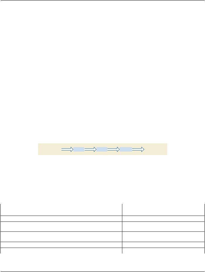
To create this view, the Volumetric Presentation State Relationship Module refers to one input volume, and uses the Volumetric​ Presentation State Display Module with a minimum set of Attributes, generating this simple pipeline:​

Scalar value

VOI LUT

Scalar value

MPR Slicing

Scalar value

Presentation LUT

P-Values


Figure XXX.3.1-1. Simple Planar MPR Pipeline​

The parameters for computing the Multi-Planar Reconstruction are defined in the Multi-Planar Reconstruction Geometry Module.​

XXX.3.1.3 Encoding Details​

XXX.3.1.3.1 Volumetric Presentation State Relationship Module Recommendations​

Table XXX.3.1-1. Volumetric Presentation State Relationship Module Recommendations​

Attribute Name​

Tag​

Comment​

VolumetricPresentationStateInputSequence​

(0070,1201)​

Set one item in this sequence.​

>Presentation Input Type​

(0070,1202)​

Set to "VOLUME".​

>Referenced Image Sequence​

(0008,1140)​

Set reference(s) to the image(s) that make up the​


input volume.​

>Window Center​

(0028,1050)​

Set either Window Center and Window Width or VOI​


LUT Sequence (0028,3010).​

>Window Width​

(0028,1051)​


>Crop​

(0070,1204)​

Set to "NO".​

- Standard -​

Page 740​

DICOM PS3.17 2020a - Explanatory Information​

XXX.3.1.3.2 Volumetric Presentation State Display Module Recommendations​

Table XXX.3.1-2. Volumetric Presentation State Display Module Recommendations​

Attribute Name​

Tag​

Comment​

Pixel Presentation​

(0008,9205)​

Set to "MONOCHROME"​

Presentation LUT Shape​

(2050,0020)​

Set to "IDENTITY" or "INVERSE"​

XXX.3.2 Spatially Related Views (e.g., Orthogonal)​

XXX.3.2.1 User Scenario​

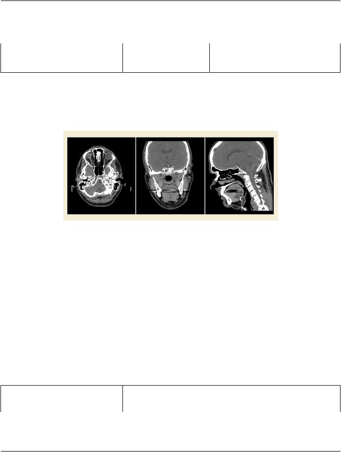
Planar MPR views are often displayed together with other spatially related Planar MPR views. For example, a very common setup​ are three orthogonal MPRs showing a lesion in transverse, coronal and sagittal views of the data.​

Figure XXX.3.2-1. Three orthogonal MPR views. From left to right transverse, coronal, sagittal​

XXX.3.2.2 Encoding Outline​

The storage of the view shown in Figure XXX.3.2-1 requires the generation of three Planar MPR VPS SOP instances and normally​ a Basic Structured Display SOP instance which references the Planar MPR VPS SOP instances.​

InordertoenabledisplayapplicationswhichdonotsupporttheBasicStructuredDisplaySOPClasstocreatesimilarviewsofmultiple​ related Planar MPRs the Planar MPR VPS SOP Class supports marking instances as spatially related in the Volumetric Presentation​ State Identification Module.​

This allows display applications to identify Volumetric Presentation State instances for viewing together. Additionally, via the View​ Modifier Code Sequence (0054, 0222) in the Presentation View Description Module, display applications can determine which Volu-​ metricPresentationStateinstancetoshowatwhichpositiononthedisplaydependingontheuserpreferences.RefertoSectionXXX.4​ for display layout considerations.​

XXX.3.2.3 Encoding Details​

XXX.3.2.3.1 Volumetric Presentation State Identification Module Recommendations​

Table XXX.3.2-1. Volumetric Presentation State Identification Module Recommendations​

Attribute Name​

Tag​

Comment​

Presentation Display Collection UID​

(0070,1101)​

Set to the same UID in all three Planar MPS VPS SOP​


Instances.​

- Standard -​

Источник: https://studfile.net/preview/14585770/