Материал: part17

Внимание! Если размещение файла нарушает Ваши авторские права, то обязательно сообщите нам

DICOM PS3.17 2020a - Explanatory Information​

Page 741​

XXX.3.2.3.2 Volumetric Presentation State Relationship Module Recommendations​

Table XXX.3.2-2. Volumetric Presentation State Relationship Module Recommendations​

Attribute Name​

Tag​

Comment​

VolumetricPresentationStateInputSequence​

(0070,1201)​


>Referenced Image Sequence​

(0008,1140)​

In this particular scenario usually all three VPS instances​


reference the same instances that create the volume from​


which the respective MPR is rendered.​

Display applications may want to implement mechanisms for detecting when VPS SOP Instances reference exactly the same image​ instances within their Volumetric Presentation State Input Sequence item which creates the volume. This saves memory by loading​ the image instances that create the volume only once.​

TheVolumetricPresentationStatesprovidenomechanismtoexplicitlyspecifythesharingofavolumebymultipleVPSSOPinstances.​

XXX.3.2.3.3 Presentation View Description Module Recommendations​

Table XXX.3.2-3. Presentation View Description Module Recommendations​

Attribute Name​

Tag​

Comment​

View Code Sequence​

(0054,0220)​

For this particular example, CID 2 “Anatomic Modifier”​


provides applicable values:​

>Code Value​

(0008,0100)​

Set to "81654009", "30730003", or "62824007"​

>Coding Scheme Designator​

(0008,0102)​

Set to "SCT"​

>Code Meaning​

(0008,0104)​

Set to "Coronal", "Sagittal", or "Transverse", respectively​

XXX.3.3 Replacing Set of Derived Images with Multiple Volumetric Presentation States​

XXX.3.3.1 User Scenario​

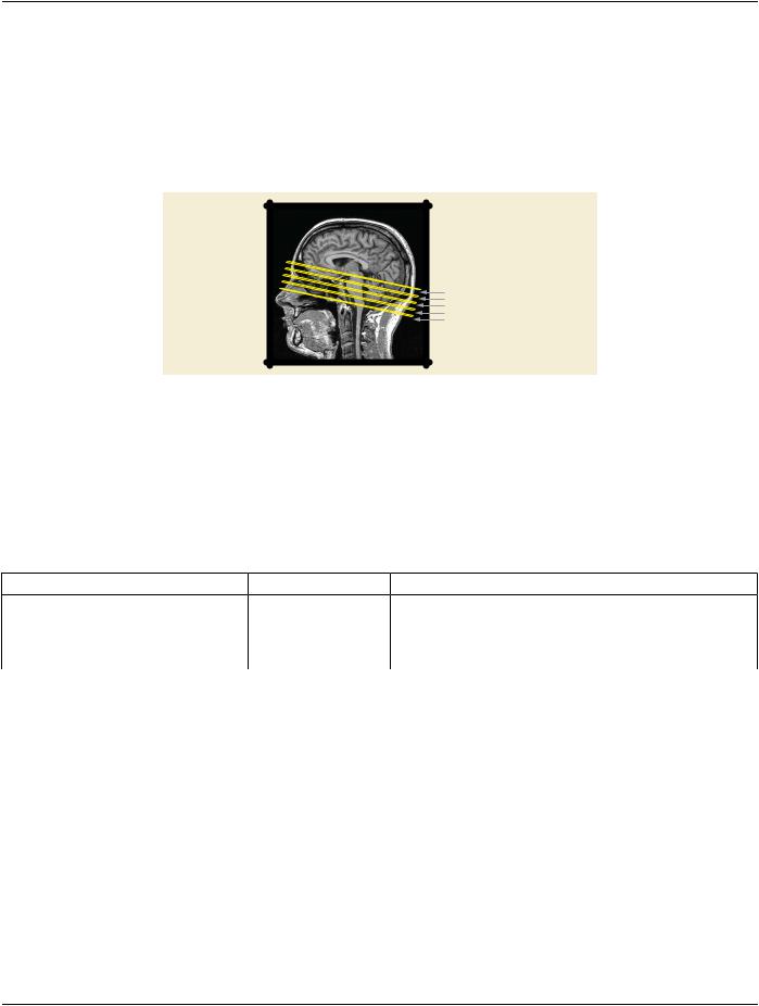
In the clinical routine radiologists often create a set of derived images from Planar MPR views that cover a specific anatomic region.​ For example from a head scan a range of oblique transverse Planar MPR views are defined. These views are rendered into separate​ derived CT or Secondary Capture SOP Class instances for conveying the relevant information to the referring clinician.​

H

A

Figure XXX.3.3-1. Definition of a range of oblique transverse Planar MPR views on sagittal view of head​

scan for creation of derived images​

However, these derived images depicting the specific anatomy cannot be changed by the display application. The referring clinician​ cannot view other anatomy not shown by the derived images and cannot alter the orientation of the Planar MPR views.​

Alternatively, a set of Planar MPR VPS SOP Instances can be created to depict the slices through the volume. To indicate that these​ Volumetric Presentation State instances are sequentially related, the Presentation Sequence Collection UID (0070,1102) is used to​

- Standard -​

Page 742​

DICOM PS3.17 2020a - Explanatory Information​

associatetheinstancestoshowtheinstancesaretobedisplayedinsequence,andeachVPSinstanceisgivenaPresentationSequence​ Position Index (0070,1103) value to indicate the order in which the instances occur in the collection (in this case, a spatial sequence).​ In this usage, no animation is specified and it is at the discretion of the display application how these views are to be presented, such​ as by frames in a light-box format or by a manual control stepping through the presentations in one display window.​

XXX.3.3.2 Encoding Outline​

For Planar MPR views that can be moved or rotated by the display application, no special encodings in the Planar MPR VPS SOP​ Instance are necessary.​


H

A

VPS Instance 5

VPS Instance 4


VPS Instance 3


VPS Instance 2


VPS Instance 1

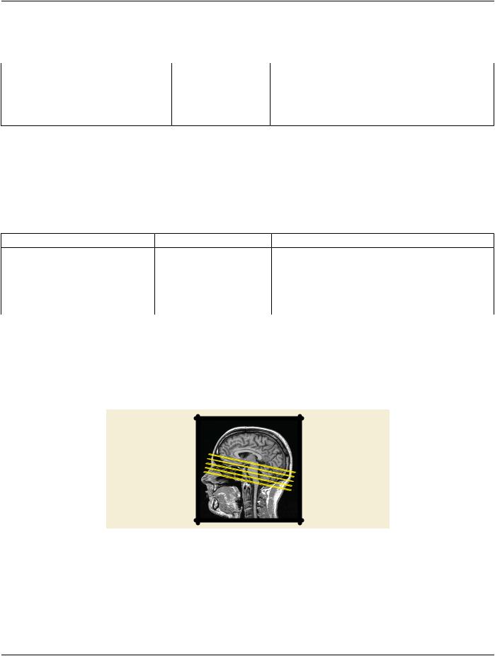
Figure XXX.3.3-2. One Volumetric Presentations States is created for each of the MPR views. The VPS​ Instances have the same value of Presentation Display Collection UID (0070,1101)​

In general, the individual VPS instances may have any orientation and be in any location.​

XXX.3.3.3 Encoding Details​

XXX.3.3.3.1 Volumetric Presentation State Identification Module Recommendations​

Table XXX.3.3-1. Volumetric Presentation State Identification Module Recommendations​

Attribute Name​

Tag​

Comment​

Presentation Sequence Collection UID​

(0070,1102)​

Set to the same UID value in each of the Presentation State​


instances indicating the views are sequentially ordered.​

Presentation Sequence Position Index​

(0070,1103)​

Set to a number indicating the order of each VPS view in the​


sequentially-ordered set.​

XXX.3.4 Replacing Set of Derived Images With Single VPS Using Crosscurve Animation​

XXX.3.4.1 User Scenario​

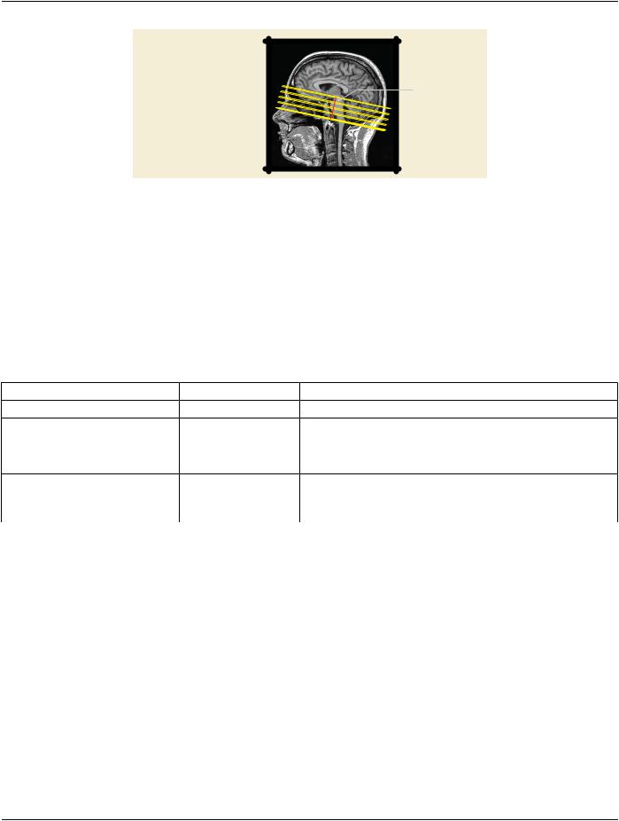
Another technique for depicting a set of derived images is to have a single Planar MPR VPS SOP Instance that describes an initial​ Planar MPR view, and specify cross-curve animation to generate the other related views. A straight-line curve is specified that begins​ at the center of the initial Planar MPR view and ends at the intended center of the last Planar MPR view of the set. A step size is​ specified to be the distance between the first and last points of the line divided by the number of desired slices minus one. A Recom-​ mended Animation Rate (0070,1A03) is specified if the creator wishes to provide a hint to the display application to scroll through the​ slices in the set, or could be omitted to leave the animation method to the discretion of the display application.​

- Standard -​

DICOM PS3.17 2020a - Explanatory Information​

Page 743​

H

Curve

MPR view defined in this VPS Instance

A

Animation Step Size

Figure XXX.3.4-1. Additional MPR views are generated by moving the view that is defined in the VPS in​ Animation Step Size (0070,1A05) steps perpendicular along the curve​

XXX.3.4.2 Encoding Outline​

For this case, the curve is a straight line. In general, however, the curve may have any form such as a circular curve to create radial​ MPR views.​

XXX.3.4.3 Encoding Details​

XXX.3.4.3.1 Presentation Animation Module Recommendations​

Table XXX.3.4-1. Presentation Animation Module Recommendations​

Attribute Name​

Tag​

Comment​

Presentation Animation Style​

(0070,1A01)​

Set to "CROSSCURVE"​

Recommended Animation Rate​

(0070,1A03)​

Set to provide a hint to the display application to automatically move​


thePlanarMPRviewalongthecurvethroughthevolume,oromitted​


to leave the animation method to the discretion of the display​


application.​

Animation Curve Sequence​

(0070,1A04)​

Set to the start point and end point of the straight-line curve.​

Animation Step Size​

(0070,1A05)​

Set to (line length / (number of slices - 1)) as the distance between​


MPR views along the straight-line curve.​

XXX.3.5 Volumetric Annotations (example: Trajectory Planning)​

XXX.3.5.1 User Scenario​

The Planar MPR Volumetric Presentation State makes it easy for the receiving display application to enable the user to modify the​ initial view for viewing nearby anatomy. This requires that display relative annotations need to be removed when the initial view gets​ manipulated. Otherwise there would be the risk that the annotations point to the wrong anatomy.​

To give the display application more control over when to show annotations, the Planar MPR Volumetric Presentation State defines​ annotations described by coordinates in the VPS-RCS.​

Asanexample,duringinterventiontrajectoryplanningoneormorestraightlinesrepresentingthetrajectoriesofadevice(e.g.,needle)​ to be introduced during further treatment (e.g., cementoplasty, tumor ablation…) are drawn by the user on a planar MPR view.​

- Standard -​

Page 744​

DICOM PS3.17 2020a - Explanatory Information​

Needle trajectory

Figure XXX.3.5-1. Needle trajectory on a Planar MPR view​

The Planar MPR VPS does not define how to render the text associated with the annotation or how to connect it to the graphical​ representation of the annotation. This is an implementation decision.​

The creating application derives the 3D coordinates of the needle trajectory from the Planar MPR view and creates a Planar MPR​ VPS SOP instance with the needle trajectory as Volumetric Graphic Annotation. When a user viewing the Presentation State manip-​ ulates the initial Planar MPR view, the display application could control the visibility of the needle trajectory based on the visibility of​ the part of the volume which is crossed by the needle trajectory (e.g., by fading the trajectory in and out, since the intersection of the​ graphic with the plane may only appear as one point). Annotation Clipping (0070,1907) controls whether the out-of-view portion of​ the 3D annotation is displayed or not; see Section C.11.28.1 “Annotation Clipping” in PS3.3 for details.​

For handling multiple annotations in different areas of the volume, applications might provide a list of the annotations which are refer-​ enced in the Presentation State. When a user selects one of the annotations the Planar MPR view could automatically be adjusted​ to optimally show the part of the volume containing the annotation.​

XXX.3.5.2 Encoding Outline​

TheVolumetricPresentationStateprovidestheVolumetricAnnotationSequence(0070,1901)fordefiningannotationsbycoordinates​

in the VPS-RCS.​

TheneedletrajectoryisencodedasalinedescribedbycoordinatesintheVPS-RCS.OptionallyaStructuredReportcanbereferenced​ in order to allow the display application to access additional clinical context.​

XXX.3.5.3 Encoding Details​

XXX.3.5.3.1 Volumetric Graphic Annotation Module Recommendations​

Table XXX.3.5-1. Volumetric Graphic Annotation Module Recommendations​

Attribute Name​

Tag​

Comment​

Volumetric Annotation Sequence​

(0070,1901)​

Set multiple items in this sequence for multiple needle trajectories, one​


item for each needle trajectory.​

>Graphic Data​

(0070,0022)​

Set to two (x,y,z) triplets, one for the start and one for the end of the​


needle trajectory line​

>Graphic Type​

(0070,0023)​

Set to "POLYLINE"​

>Graphics Layer​

(0070,0002)​

Set the same layer for all annotations of the same style.​

>Annotation Clipping​

(0070,1907)​

Set to YES if only the portion of the 3D Annotation within the MPR slice​


or slab is to be displayed.​


SettoNOifthe3DAnnotationoutsidetheMPRsliceorslabshouldalso​


be projected into the view.​

>Unformatted Text Value​

(0070,0006)​

Set "Needle trajectory" as the text to show as a label next to the graphic​


annotation.​

- Standard -​


DICOM PS3.17 2020a - Explanatory Information​

Page 745​

Attribute Name​

Tag​

Comment​


>Referenced Structured Context​

(0070,1903)​

Set to a reference to a Structured Report and a Content Item providing​

Sequence​


clinical meaning of the annotation.​


The display application could make additional text from the referenced​ Structured Report concept separately available to the user (e.g., on​ mouse-over).​

XXX.3.6 Highlighting Areas of Interest in MPR View​

XXX.3.6.1 User Scenario​

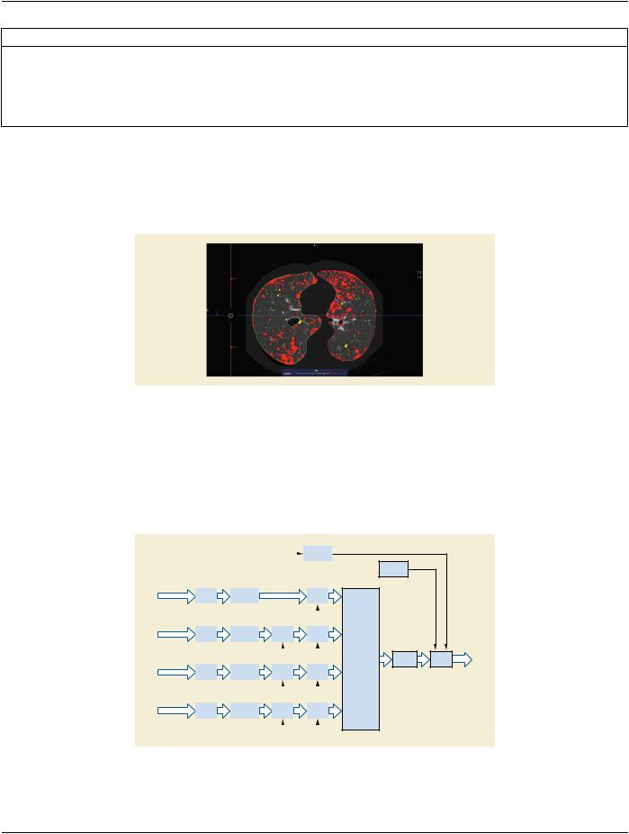
Lung nodules in a volume have been classified by a Computer Aided Detection mechanism into different categories. E.g. small, me-​ dium, large. In planar MPR views the nodules are colorized according to their classification.​

Figure XXX.3.6-1. Planar MPR View with Lung Nodules Colorized by Category​

XXX.3.6.2 Encoding Outline​

The classification of the lung nodules is stored in one or multiple Segmentation IOD instances. For each lung nodule category one​ Segmentation marks the corresponding areas in the volume.​

Forexample,tocreateaPlanarMPRviewwhichshows3lungnodulecategoriesindifferentcolorsthePlanarMPRVPSIODinstance​ defines via the Volumetric Presentation State Display Module a volumetric pipeline with 4 inputs.​

Volume graphics input


MPR and


Projection


Lung Volume


VOI LUT


Spatial


MPR


Registration


MPR Geometry


Lung Volume


VOI LUT


Spatial


Cropping


MPR


Registration


Large Nodule Segmentation


MPR Geometry


Lung Volume


VOI LUT


Spatial


Cropping


MPR


Registration


Medium Nodule Segmentation


MPR Geometry


Lung Volume


VOI LUT


Spatial


Cropping


MPR


Registration


Small Nodule Segmentation


MPR Geometry


Graphic


Annotation


Volumetric

PCS

Graphics


Presentation

PCS

State Display

Transform

Layer


Figure XXX.3.6-2. Planar MPR VPS Pipeline for Colorizing the Lung Nodule Categories​

The same volume data of the lung is used as input for all sub pipelines:​

- Standard -​

Источник: https://studfile.net/preview/14585770/