Материал: part17

|
DICOM PS3.17 2020a - Explanatory Information |
|
Page 181 |
||
Nest |
Code Meaning of Concept Name |
Code Meaning or Example |
|
TID |
|
|
|
|
Value |
|
|
>> |
Finding Site |
|
Left Ventricle |
TID 5202 |
|
>> |
Measurement Group |
|
|
TID 5202 |
|
>> |
Image Mode |
|
2D |
TID 5202 |
|
>>> |
Heart Rate |
|
89 bpm |
TID 5202 |
|
>>> |
Left Ventricular End Diastolic Volume |
38.914 ml |
TID 5202 |
|
|
>>>> |
Measurement Method |
|
Teichholz |
TID 5202 |
|
>>> |
Left Ventricular End Systolic Volume |
|
12.304 ml |
TID 5202 |
|
>>>> |
Measurement Method |
|
Teichholz |
TID 5202 |
|
… |
… |
|
… |
… |
|
>>> |
Stroke Volume |
|
26.6 ml |
TID 5202 |
|
>>>> |
Anatomic Site |
|
Left Ventricle |
TID 5202 |
|
>>> |
Stroke Index |
|
13.49 ml/m2 |
TID 5202 |
|
>>>> |
Anatomic Site |
|
Left Ventricle |
TID 5202 |
|
>>> |
Cardiac Output |
|
2.37 l/min |
TID 5202 |
|
>>>> |
Anatomic Site |
|
Left Ventricle |
TID 5202 |
|
>>> |
Cardiac Index |
|
1.20 l/min/m2 |
TID 5202 |
|
>>>> |
Anatomic Site |
|
Left Ventricle |
TID 5202 |
|
>>>> |
Index |
|
BSA |
TID 5202 |
|
>>> |
Left Ventricular Ejection Fraction |
|
68.4 % |
TID 5202 |
|
>>> |
… |
|
|
… |
|
N.4.6 Example 6: Wall Scoring |
|
|
|
|
|
Nest |
Code Meaning of Concept Name |
Code Meaning or Example Value |
TID |
||
|
Adult Echocardiography Procedure |
|
|
TID 5200 |
|
|
Report |
|
|
|
|
> |
…. |
|
|
… |
|
> |
Findings |
|
|
TID 5204 |
|
>> |
Procedure Reported |
Echocardiography for DeterminingTID 5204 |
|
||
|
|
Ventricular Contraction |
|
|
|
>> |
Stage |
Pre-stress image acquisition |
TID 5204 |
|
|
>> |
LV Wall Motion Score Index |
1.0 |
TID 5204 |
|
|
>>> |
Assessment Scale |
5 Point Segment Finding Scale |
TID 5204 |
|
|
>> |
Findings |
|
|
TID 5204 |
|
>>> |
Wall Segment |
Basal anterior |
TID 5204 |
|
|
>>>> |
Wall motion finding |
Normal |
TID 5204 |
|
|
>>> |
Wall Segment |
Basal anteroseptal |
TID 5204 |
|
|
>>>> |
Wall motion finding |
Normal |
TID 5204 |
|
|
>>> |
Wall Segment |
Basal inferoseptal |
TID 5204 |
|
|
>>>> |
Wall motion finding |
Akinetic |
TID 5204 |
|
|
… |
… remaining segments … |
|
|
TID 5204 |
|
> |
Wall Motion Analysis |
|
|
TID 5204 |
|
- Standard -
Page 182 |
DICOM PS3.17 2020a - Explanatory Information |
|
|
|
Nest |
Code Meaning of Concept Name |
Code Meaning or Example Value |
TID |
|
>> |
Stage |
Peak-stress image acquisition |
TID 5204 |
|
>> |
LV Wall Motion Score Index |
1.23 |
TID 5204 |
|
>>> |
Assessment Scale |
5 Point Segment Finding Scale |
TID 5204 |
|
>> |
Findings |
|
TID 5204 |
|
>>> |
Wall Segment |
Basal anterior |
TID 5204 |
|
>>>> |
Score |
Hypokinesis |
TID 5204 |
|
>>> |
Wall Segment |
Basal anteroseptal |
TID 5204 |
|
>>>> |
Score |
Akinetic |
TID 5204 |
|
>>>> |
Morphology |
Scar / Thinning |
TID 5204 |
|
>>> |
Wall Segment |
Basal inferoseptal |
TID 5204 |
|
>>>> |
Score |
Normal |
TID 5204 |
|
… |
… remaining segments … |
|
TID 5204 |
|
N.5 IVUS Report
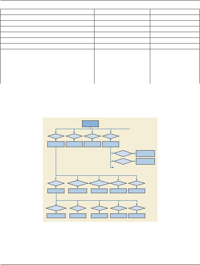
The IVUS Report contains one or more vessel containers, each corresponding to the vessel (arterial location) being imaged. Each vessel is associated with one or more IVUS image pullbacks (Ultrasound Multi-frame Images), acquired during a phase of a catheter- ization procedure. Each vessel may contain one or more sub-containers, each associated with a single lesion. Each lesion container includes a set of IVUS measurements and qualitative assessments. The resulting hierarchical structure is depicted in Figure N.5-1.
|
|
IVUS Report |
|
|
|
(CONTAINER) |
|
CONTAINS |
CONTAINS |
CONTAINS |
CONTAINS |
Vessel |
Vessel |
Vessel |
Image Library |
(CONTAINER) |
(CONTAINER) |
(CONTAINER) |
(CONTAINER) |
CONTAINS
Image Reference
IMAGE
CONTAINS
Image Reference
IMAGE
CONTAINS |
HAS OBS CONTEXT |
HAS OBS CONTEXT |
CONTAINS |
CONTAINS |
|
Lesion |
Arterial Location |
Procedure Phase |
Vessel Morphology |
Vessel Findings |
|
(CONTAINER) |
|||||
|
|
|
|
||
HAS OBS CONTEXT |
CONTAINS |
CONTAINS |
CONTAINS |
CONTAINS |
|
Lesion Location |
Qualitative |
IVUS Measurements |
Device Used |
Findings |
|
Assessments |
|||||
|
|
|
|
Figure N.5-1. IVUS Report Structure
- Standard -
DICOM PS3.17 2020a - Explanatory Information |
Page 183 |
O Registration (Informative)
O.1 Spatial Registration and Spatial Fiducials SOP Classes
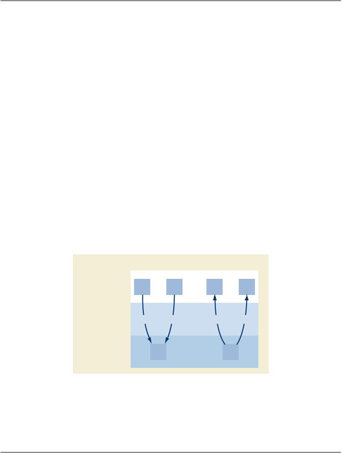
These SOP Classes allow describing spatial relationships between sets of images. Each instance can describe any number of regis- trations as shown in Figure O.1-1. It may also reference prior registration instances that contribute to the creation of the registrations in the instance.
A Reference Coordinate System (RCS) is a spatial Frame of Reference described by the DICOM Frame of Reference Module. The chosen Frame of Reference of the Registration SOP Instance may be the same as one or more of the Referenced SOP Instances. In this case, the Frame of Reference UID (0020,0052) is the same, as shown by the Registered RCS in the figure. The registration information is a sequence of spatial transformations, potentially including deformation information. The composite of the specified spatial transformations defines the complete transformation from one RCS to the other.
Image instances may have no DICOM Frame of Reference, in which case the registration is to that single image (or frame, in the case of a Multi-frame Image). The Spatial Registration IOD may also be used to establish a coordinate system for an image that has no defined Frame of Reference. To do this, the center of the top left pixel of the source image is treated as being located at (0, 0, 0). Offsets from the first pixel are computed using the resolution specified in the Source IOD. Multiplying that coordinate by the Trans- formation matrix gives the patient coordinate in the new Frame of Reference.
A special case is an atlas. DICOM has defined Well-Known Frame of Reference UIDs for several common atlases. There is not ne- cessarily image data associated with an atlas.
WhenusingtheSpatialRegistrationorDeformableRegistrationSOPClassestherearetwotypesofcoordinatesystems.Thecoordinate system of the referenced data is the Source RCS. The coordinate system established by the SOP instance is the Registered RCS.
ThesenseofthedirectionoftransformationdiffersbetweentheSpatialRegistrationSOPClassandtheDeformableSpatialRegistration SOP Class. The Spatial Registration SOP Class specifies a transformation that maps Source coordinates, in the Source RCS, to Registered coordinates, in the Registered RCS. The Deformable Spatial Registration SOP Class specifies transformations that map Registered coordinates, in the Registered RCS, to coordinates in the Source RCS.
The Spatial Fiducials SOP Class stores spatial fiducials as implicit registration information.
Spatial Registration |
Deformable |
|
Spatial Registration |
||
|
SOURCE |
RCS-1 |
|
RCS-2 |
|
RCS-1 |
|
RCS-2 |
|
|
|
|
|
|
|
|
TRANSFORMATIONS |
M1T |
M2T |
Δ+M3T |
Δ+M4T |
REGISTERED |
RCS-1 |
|
RCS-2 |
|
|
|
|
Figure O.1-1. Registration of Image SOP Instances
O.2 Functional Use Cases
Multi-Modality Fusion: A workstation or modality performs a registration of images from independent acquisition modalities-PET, CT, MR, NM, and US-from multiple series. The workstation stores the registration data for subsequent visualization and image pro- cessing. Such visualization may include side-by-side synchronized display, or overlay (fusion) of one modality image on the display
- Standard -
Page 184 |
DICOM PS3.17 2020a - Explanatory Information |
of another. The processes for such fusion are beyond the scope of the Standard. The workstation may also create and store a ready- for-displayfusedimage,whichreferencesboththesourceimageinstancesandtheregistrationinstancethatdescribestheiralignment.
Prior Study Fusion: Using post processing or a manual process, a workstation creates a spatial object registration of the current Study's Series from prior Studies for comparative evaluation.
AtlasMapping:AworkstationoraCADdevicespecifiesfiducialsofanatomicalfeaturesinthebrainsuchastheanteriorcommissure, posteriorcommissure,andpointsthatdefinethehemisphericfissureplane.ThesystemstoresthisinformationintheSpatialFiducials SOP Instance. Subsequent retrieval of the fiducials enables a device or workstation to register the patient images to a functional or anatomical atlas, presenting the atlas information as overlays.
CAD: A CAD device creates fiducials of features during the course of the analysis. It stores the locations of the fiducials for future analysis in another imaging procedure. In the subsequent CAD procedure, the CAD device performs a new analysis on the new data. As before, it creates comparable fiducials, which it may store in a Spatial Fiducials SOP Instance. The CAD device then performs additional analysis by registering the images of the current exam to the prior exam. It does so by correlating the fiducials of the prior and current exam. The CAD device may store the registration in Registration SOP Instance.
Adaptive Radiotherapy: A CT Scan is taken to account for variations in patient position prior to radiation therapy. A workstation performs the registration of the most recent image data to the prior data, corrects the plan, and stores the registration and revised plan.
Image Stitching: An acquisition device captures multiple images, e.g., DX images down a limb. A user identifies fiducials on each oftheimages.ThesystemstorestheseinoneormoreFiducialSOPInstances.Thentheimagesare"stitched"togetheralgorithmically by means that utilize the Fiducial SOP Instances as input. The result is a single image and optionally a Registration SOP Instance that indicates how the original images can be transformed to a location on the final image.
O.3 System Interaction
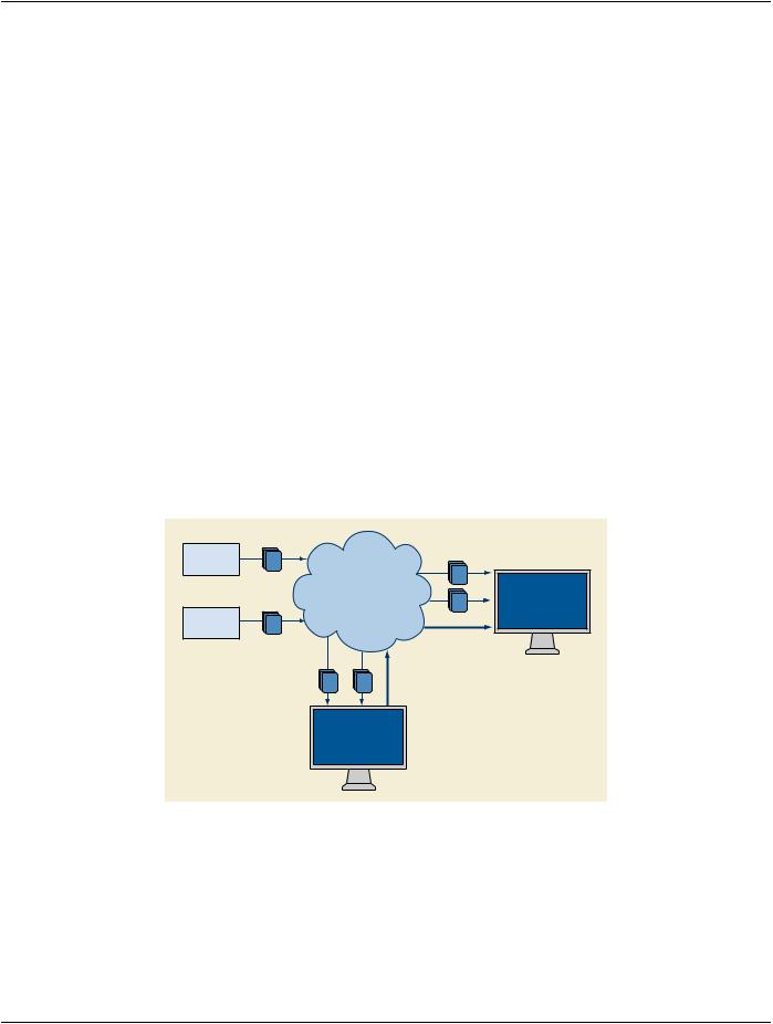
Figure O.3-1 shows the system interaction of storage operations for a registration of MR and CT using the Spatial Registration SOP Class. The Image Plane Module Attributes of the CT Series specify the spatial mapping to the RCS of its DICOM Frame of Reference.
Modality CT
CT
Information
Network Workstation
MR
or CAD
Modality |
MR |
Registration |
CT MR Registration
Workstation
or CAD
Figure O.3-1. Stored Registration System Interaction
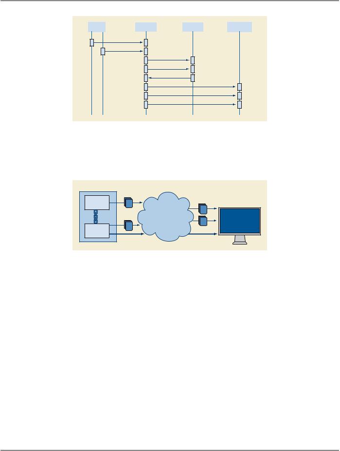
The receiver of the Registration SOP Instance may use the spatial transformation to display or process the referenced image data in a common coordinate system. This enables interactive display in 3D during interpretation or planning, tissue classification, quantific- ation, or Computer Aided Detection. Figure O.3-2 shows a typical interaction scenario.
- Standard -
DICOM PS3.17 2020a - Explanatory Information |
Page 185 |
Modality |
|
Storage |
|
Registration |
|
Visualization |
|
A |
B |
|
Device |
|
Device |
|
Device |
|
|
|
|
|
|
|
|
Images A
Images B
Images A
Images B
Registration
Images A
Images B
Registration
Figure O.3-2. Interaction Scenario
In the case of coupled acquisition modalities, one acquisition device may know the spatial relationship of its image data relative to the other. The acquisition device may use the Registration SOP Class to specify the relationship of modality B images to modality A imagesasshownbelowinFigureO.3-3.Inthemostdirectcase,thedataofbothmodalitiesareinthesameDICOMFrameofReference for each SOP Class Instance.
Coupled Modalities |
|
|
|
Modality |
A |
|
|
|
|
A |
|
|
Information |
|
|
|
Network |
B |
Workstation |
|
|
or CAD |
|
|
B |
|
|
|
|
|
|
Modality |
|
|
|
|
Registration |
Registration |
|
Figure O.3-3. Coupled Modalities
A Spatial Registration instance consists of one or more instances of a Registration. Each Registration specifies a transformation from theRCSoftheReferencedImageSet,totheRCSofthisSpatialRegistrationinstance(seePS3.3)identifiedbytheFrameofReference UID (0020,0052).
O.4 Overview of Encoding
Figure O.4-1 shows an information model of a Spatial Registration to illustrate the relationship of the Attributes to the objects of the model. The DICOM Attributes that describe each object are adjacent to the object.
- Standard -