Материал: part17

Внимание! Если размещение файла нарушает Ваши авторские права, то обязательно сообщите нам


DICOM PS3.17 2020a - Explanatory Information​

Page 451​

Node​

Code Meaning of Concept Name​

Code Meaning or Example​

TID​


Value​


1.4.2.1.3​

Mating Feature ID​

1​

TID 7000​

1.4.2.2​

Connected Implantation Plan Component​

TID 7000​

1.4.2.2.1​

Component ID​

1​

TID 7000​

1.4.2.2.2​

Mating Feature Set ID​

1​

TID 7000​

1.4.2.2.3​

Mating Feature ID​

2​

TID 7000​

1.4.3​

Component Connection​


TID 7000​

1.4.3.1​

Connected Implantation Plan Component​

TID 7000​

1.4.3.1.1​

Component ID​

2​

TID 7000​

1.4.3.1.2​

Mating Feature Set ID​

2​

TID 7000​

1.4.3.1.3​

Mating Feature ID​

1​

TID 7000​

1.4.3.2​

Connected Implantation Plan Component​

TID 7000​

1.4.3.2.1​

Component ID​

4​

TID 7000​

1.4.3.2.2​

Mating Feature Set ID​

2​

TID 7000​

1.4.3.2.3​

Mating Feature ID​

2​

TID 7000​

1.5​

Information used for planning​


TID 7000​

1.5.1​

Patient Image​

Reference to Image 01​

TID 7000​

1.5.1.2​

Horizontal Pixel Spacing​

0.2 mm/pixel​

TID 7000​

1.5.1.3​

Vertical Pixel Spacing​

0.2 mm/pixel​

TID 7000​

1.6​

Planning Information for Intraoperative​

TID 7000​


Usage​


1.6.1​

Supporting Information​

Reference to Encapsulated​

TID 7000​


PDF-Document 01​


1.6.2​

Derived Images​

Reference to Visualization 01​ TID 7000​

AAA.4 Implantation Plan SR Document Dental Drilling Template Example​

The following example shows the result of a planning activity for a dental implantation using a dental drilling template. The implant​ positioning is based on a CT-Scan during which the patient has been wearing a bite plate with 3 markers. In this example the markers​ (visible in the patient's CT images) are detected by the planning application. After the implants have been positioned, the bite plate,​ in combination with the registration information of the implants, can be used to produce the dental drilling template.​

In the following example, two implants are inserted that are not assembled using Mating Points.​

The markers of the bite plate are identified and stored as 3 Fiducials in one Fiducial Set. This Fiducial Set has its own Frame of Ref-​ erence (1.2.3.4.100).​

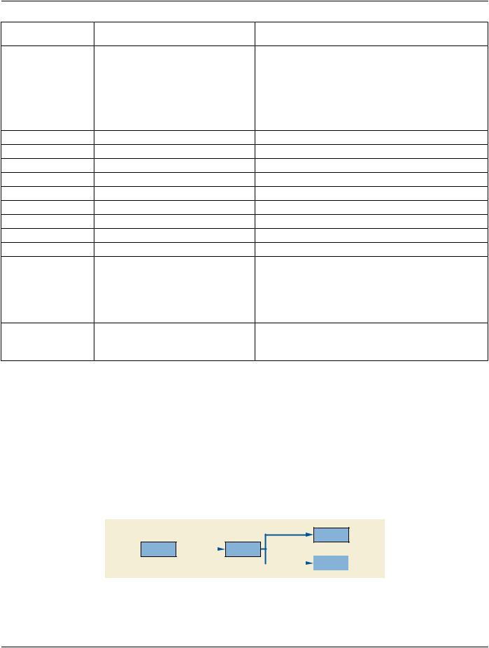
The Registration Object created by the planning application uses the patient's CT Frame of Reference as main Frame of Reference​ (see Figure AAA.4-1).​

Spatial Relation

Implant

Patient

Spatial Relation

Bite Plate

(CT Image)


Spatial Relation


Dental Drilling


Template


Figure AAA.4-1. Spatial Relations of Implant, Implant Template, Bite Plate and Patient CT​

- Standard -​

Page 452​ DICOM PS3.17 2020a - Explanatory Information​

Table AAA.3-2. Dental Drilling Template Example​

Node​

Code Meaning of Concept Name​

Code Meaning or Example Value​

TID​

1​

Implantation Plan​


TID 7000​


1.1​

Language of Content Item and​

English​

TID 1204​


Descendants​


1.2​

Observation Context​


TID 1001​


1.2.1​

Person Observer Name​

Dr. Michael Mueller​

TID 1003​


1.2.2​

Subject Name​

John Smith​

TID 1007​


1.2.3​

Subject ID​

1.2.3.4.5.6.7.8.9​

TID 1007​


1.2.4​

Subject Species​

(337915000, SCT, "homo sapiens")​TID 1007​


1.3​

Implant Component List​


TID 7000​


1.3.1​

Selected Implant Component​


TID 7000​


1.3.1.1​

Component ID​

1​

TID 7000​


1.3.1.2​

Component Type​

112305​

TID 7000​


1.3.1.3​


Reference to Implant Template​

TID 7000​


"DI1000" (derived)​


1.3.1.4​

Frame Of Reference UID​

1.2.3.4.1​

TID 7000​


1.3.1.5​

Manufacturer Implant Template​

Reference to Implant Template​

TID 7000​


"DI1000" (original)​


1.3.2​

Implant Component Selection​


TID 7000​


1.3.2.1​

Component ID​

2​

TID 7000​


1.3.2.2​

Component Type​

(112306, DCM, "Acetabular Cup​

TID 7000​


Insert")​


1.3.2.3​


Reference to Implant Template​

TID 7000​


"DI2000" (derived)​


1.3.2.4​

Frame Of Reference UID​

1.2.3.4.2​

TID 7000​


1.3.2.5​

Manufacturer Implant Template​

Reference to Implant Template​

TID 7000​


"DI2000" (original)​


1.4​

Information used for planning​


TID 7000​


1.4.1​

Patient Image​

Reference to CT Image01​

TID 7000​


1.4.1.2​

Horizontal Pixel Spacing​

0.3 mm/pixel​

TID 7000​


1.4.1.3​

Vertical Pixel Spacing​

0.3 mm/pixel​

TID 7000​


1.5​

PlanningInformationforIntraoperative​

TID 7000​


Usage​


1.5.1​

Derived Planning Images​

Reference to Visualization01​

TID 7000​


1.5.2​

Spatial Registration​

Reference to Registration01​

TID 7000​


1.5.2.1​

Frame Of Reference UID​

1.2.3.4.1​

TID 7000​


1.5.2.2​

Frame Of Reference UID​

1.2.3.4.2​

TID 7000​


1.5.2.3​

Frame Of Reference UID​

1.2.3.4.3​

TID 7000​


1.5.2.4​

Frame Of Reference UID​

1.2.3.4.100​

TID 7000​


1.5.3​

Derived Planning Data​

Reference to Fiducial 01​

TID 7000​


1.5.3.1​

Derived Fiducial​

1.2.3.4.3​

TID 7000​


1.5.3.1.1​

Fiducial Intent​

Bite Plate Marker​

TID 7000​


1.5.3.2​

Derived Fiducial​

1.2.3.4.4​

TID 7000​


- Standard -​


DICOM PS3.17 2020a - Explanatory Information​


Page 453​

Node​

Code Meaning of Concept Name​

Code Meaning or Example Value​

TID​

1.5.3.2.1​

Fiducial Intent​

Bite Plate Marker​

TID 7000​


1.5.3.3​

Derived Fiducial​

1.2.3.4.5​

TID 7000​


1.5.3.3.1​

Fiducial Intent​

Bite Plate Marker​

TID 7000​


- Standard -​

Page 454​

DICOM PS3.17 2020a - Explanatory Information​

- Standard -​

DICOM PS3.17 2020a - Explanatory Information​

Page 455​

BBBUnifiedProcedureStepinRadiotherapy​ (Informative)​

BBB.1 Purpose of this Annex​

ThisannexprovidesexamplesofmessagesequencingwhenusingtheUnifiedProcedureStepSOPClassesinaradiotherapycontext.​ Thissectionisnotintendedtoprovideanexhaustivesetofusecasesbutratheraninformativeexample.Thereareothervalidmessage​ sequences that could be used to obtain an equivalent outcome and there are other valid combinations of actors that could be involved​ in the workflow management.​

The current use cases assume that tasks are always scheduled by the scheduler prior to being performed. It does not address the​ use case of an emergency or otherwise unscheduled treatment, where the procedure step will be created by a different device.​ However, Unified Procedure Step does provide a convenient mechanism for doing this.​

The use cases addressed in this annex are:​

•​Treatment Delivery Normal Flow - Treatment Delivery System (TDS) performs the treatment delivery that was scheduled by the​ Treatment Management System (TMS). Both the "internal verification" and "external verification" flavors are modeled in these use​ cases.​

•​Treatment Delivery - Override or Additional Information Required. Operating in the external verification mode, the Machine Para-​ meter Verifier (MPV) detects an out-of-tolerance parameter of missing information, and requests the user to override the parameter​ or supply or correct the missing information. This use case addresses the situation where the 'verify' function is split from the TDS,​ but does not address verification of a subset of parameters by an external delivery accessory such as a patient positioner.​

BBB.2 Use Case Actors​

The following actors are used in the use cases below:​

User​

Human being controlling the delivery of the treatment.​

Archive​

Stores SOP Instances (images, plans, structures, dose distributions, etc).​

TreatmentManagementSystem​Manages worklists and tracks performance of procedures. This role is commonly filled by a​ (TMS)​ TreatmentManagementSystem(OncologyInformationSystem)intheOncologyDepartment.Acts​ as a UPS Pull SCP. The TMS has a user interface that may potentially be located in the treatment​

delivery control area. In addition, TMS terminals may be located throughout the institution.​

Treatment Delivery System​ Performs the treatment delivery specified by the worklist, updating a UPS, and stores treatment​ (TDS)​ records and related SOP Instances such as verification images. Acts as a UPS Pull SCU. The​ TDS user interface is dedicated to the safe and effective delivery of the treatment, and is located​

in the treatment control area, typically just outside the radiation bunker.​

Machine Parameter Verifier​ Oversees and potentially inhibits delivery of the treatment. This role is commonly filled by a​ (MPV)​ Treatment Management System in the Oncology Department, when the TDS is in the external​ verification mode. The MPV does not itself act as a UPS Pull SCU, but communicates directly with​ the TDS, which acts as a UPS Pull SCU. The MPV user interface may be shared with the TMS (in​

the treatment delivery control area), or could be located on a separate console.​

- Standard -​

Источник: https://studfile.net/preview/14585770/