Материал: part17

Внимание! Если размещение файла нарушает Ваши авторские права, то обязательно сообщите нам

Page 446​

DICOM PS3.17 2020a - Explanatory Information​

- Standard -​

DICOM PS3.17 2020a - Explanatory Information​

Page 447​

AAA Implantation Plan SR Document​ (Informative)​

Fortheimplantationofbonemountedimplants,informationthathasbeengeneratedduringtheimplantationplanningphaseisneeded​ intheOR.ToconveythisinformationtotheOR,aDICOMformatfortheresultsofanimplantationplanningactivityreferringtoimplant​ templates has been introduced. An Implantation Plan SR Document should be utilized by surgeons, navigation devices, and for doc-​ umentation purposes. The Plan contains relevant intraoperative information concerning the assembly of the implant components,​ resection lines, registration information, and relevant patient data. Thus, the Implantation Plan SR Document can help to enhance​ information logistics within the workflow. It does not contain any information about the planned surgical workflow. This information​ may be addressed by other DICOM Supplements. Nevertheless, this SR document may reference to or may be referenced by objects​ containing workflow information.​

Additionally, once an implantation plan has been generated, it can be used as input for a planning application to facilitate adaption​ of a plan in cases where this is necessary due to unforeseen situations.​

The workflow is considered to be the following:​

Some kind of planning application helps the user to perform implantation planning; he can choose the optimal implant for a patient​ using implant templates from a repository. The user aligns the implant template with patient data with or without the help of the applic-​ ation. (Planning without patient data can be stored in the Implantation Plan SR Document as well.)​

Subsequently, an Implantation Plan SR Document Instance will be created that contains the results of the planning. No information​ of the process itself (previously chosen implant templates, methods, etc.) will be stored. However, an Implantation Plan Document is​ considered to contain the important parameters to retrace a planning result.​

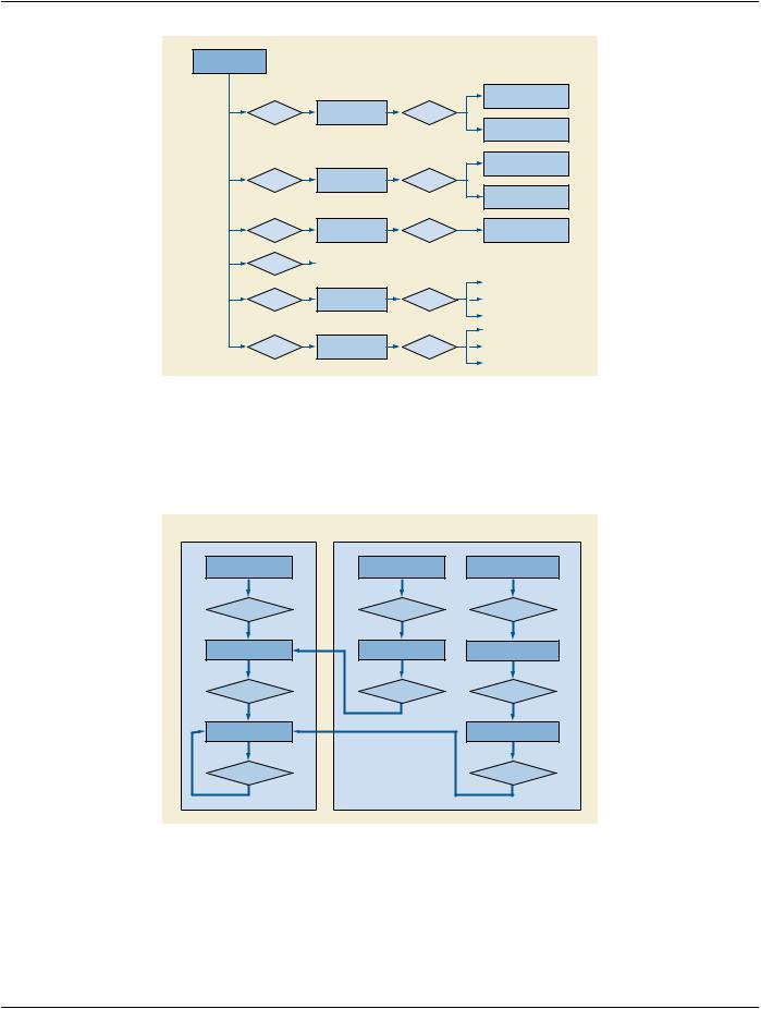
TherearetwomaincomponentsanImplantationPlanSRDocumentconsistsof(seeFigureAAA.1-1).Theimplantcomponentselection​ is used to point to a selected implant template in the repository, whereas the assembly is used to describe the composition of the​ selected implant templates. Figure AAA.2-1 shows how the Implantation Plan SR Document parts make references to the implant​ templates. Each Implantation Plan SR Document can contain a single implant component selection and several assemblies but it​ describes only one planning result for one particular patient.​

The recipient of the Implantation Plan SR Document can decide whether to read only the "list" of used implants or to go into detail​ and read the compositions as well. In both cases, he must have access to the repository of the Implant Templates to get detailed in-​ formation about the implant (such as its geometry).​

AAA.1 Implantation Plan SR Document Content Tree Structure​

ThefollowingstructureshowsthemaincontentofanImplantationPlanSRDocument.AscanbeseeninFigureAAA.1-1,theImplant-​ ation Plan consists mainly of the selected Implant Components and their Assemblies.​

- Standard -​

Page 448​

DICOM PS3.17 2020a - Explanatory Information​

Document Root

(CONTAINER)

CONTAINS

Implant Component List

CONTAINS

(CONTAINER)


CONTAINS

Assembly

CONTAINS

(CONTAINER)


CONTAINS

Assembly

CONTAINS

(CONTAINER)


CONTAINS


Planning Information


CONTAINS

for Intraoperative Usage

CONTAINS


(CONTAINER)


Information used


CONTAINS

for planning

CONTAINS


(CONTAINER)


Selected Implant Component

(CONTAINER)

Selected Implant Component

(CONTAINER)

Component Connection

(CONTAINER)

Component Connection

(CONTAINER)

Component Connection

(CONTAINER)

Figure AAA.1-1. Implantation Plan SR Document basic content tree​

AAA.2 Relationship Between Implant Template and Implantation Plan​

TheImplantationPlanSRDocumentistightlyrelatedtoImplantationTemplates(seePS3.3andPS3.16).ThefollowingFigureAAA.2-​ 1 shows the relationship between the Implant Templates and the Implantation Plan.​

Implant Template

Implantation Plan


Implant Template

Implant Component

Assembly

Repository

List


Contains

Contains

Contains

Implant Template

Selected Implant

Component Connection

Component


has

references

contains

Mating Feature


Connected Implantation


Plan Component


neighbor of


references

Figure AAA.2-1. Implantation Plan SR Document and Implant Template Relationship Diagram​

AAA.3 Implantation Plan SR Document Total Hip Replacement Example​

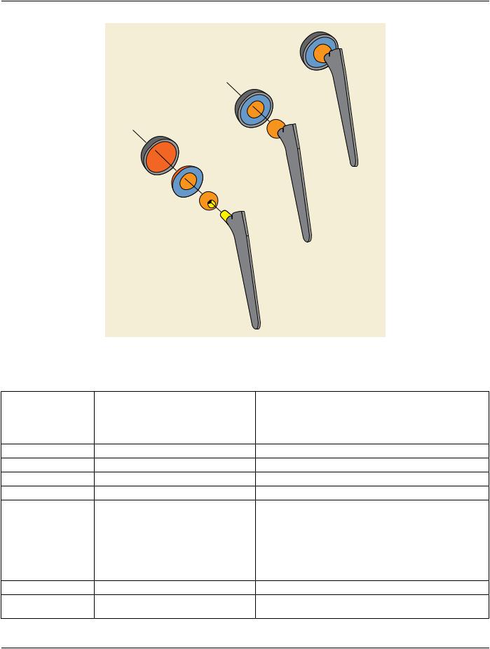
The following example shows the planning result of a simple THR (Total Hip Replacement) without any registration information. One​ Patient Image was used and one visualization was produced. One Femoral Stem, one Femoral Head, one Acetabular Bearing Insert​ and one Acetabular Fixation Cup were selected to be implanted (see Figure AAA.3-1).​

- Standard -​

DICOM PS3.17 2020a - Explanatory Information​

Page 449​

Figure AAA.3-1. Total Hip Replacement Components​

Table AAA.3-1. Total Hip Replacement Example​

Node​

Code Meaning of Concept Name​

Code Meaning or Example​

TID​


Value​


1​

Implantation Plan​


TID 7000​

1.1​

LanguageofContentItemandDescendants​English​

TID 1204​

1.2​

Observation Context​


TID 1001​

1.2.1​

Person Observer Name​

Dr. Michael Mueller​

TID 1003​

1.2.2​

Subject Name​

John Smith​

TID 1007​

1.2.3​

Subject ID​

1.2.3.4.5.6.7.8.9​

TID 1007​

1.2.4​

Subject Species​

(337915000, SCT, "homo​

TID 1007​


sapiens")​


1.3​

Implant Component List​


TID 7000​

1.3.1​

Implant Assembly Template​

Reference to THR​

TID 7000​

1.3.2​

Selected Implant Component​


TID 7000​

1.3.2.1​

Component ID​

1​

TID 7000​

1.3.2.2​

Component Type​

112310​

TID 7000​

1.3.2.3​


Reference to Implant Template​TID 7000​


"FS1000" (derived)​


- Standard -​

Page 450​

DICOM PS3.17 2020a - Explanatory Information​


Node​

Code Meaning of Concept Name​

Code Meaning or Example​

TID​


Value​


1.3.2.4​

Frame Of Reference UID​

1.2.3.4.1​

TID 7000​

1.3.2.5​

Manufacturer Implant Template​

Reference to Implant Template​TID 7000​


"FS1000" (original)​


1.3.3​

Selected Implant Component​


TID 7000​

1.3.3.1​

Component ID​

2​

TID 7000​

1.3.3.2​

Component Type​

(304121006, SCT, "Femoral​

TID 7000​


Head Prosthesis")​


1.3.3.3​


Reference to Implant Template​TID 7000​


"FH2000" (derived)​


1.3.3.4​

Frame Of Reference UID​

1.2.3.4.2​

TID 7000​

1.3.3.5​

Manufacturer Implant Template​

Reference to Implant Template​TID 7000​


"FH2000" (original)​


1.3.4​

Selected Implant Component​


TID 7000​

1.3.4.1​

Component ID​

3​

TID 7000​

1.3.4.2​

Component Type​

112305​

TID 7000​

1.3.4.3​


Reference to Implant Template​TID 7000​


"AFC3000" (derived)​


1.3.4.4​

Frame Of Reference UID​

1.2.3.4.3​

TID 7000​

1.3.4.5​

Manufacturer Implant Template​

Reference to Implant Template​TID 7000​


"AFC3000" (original)​


1.3.5​

Selected Implant Component​


TID 7000​

1.3.5.1​

Component ID​

4​

TID 7000​

1.3.5.2​

Component Type​

(112306,DCM,"AcetabularCup​TID 7000​


Insert")​


1.3.5.3​


Reference to Implant Template​TID 7000​


"ABI4000" (derived)​


1.3.5.4​

Frame Of Reference UID​

1.2.3.4.4​

TID 7000​

1.3.5.5​

Manufacturer Implant Template​

Reference to Implant Template​TID 7000​


"ABI4000" (original)​


1.4.​

Assembly​


TID 7000​

1.4.1​

Component Connection​


TID 7000​

1.4.1.1​

Connected Implantation Plan Component​

TID 7000​

1.4.1.1.1​

Component ID​

3​

TID 7000​

1.4.1.1.2​

Mating Feature Set ID​

1​

TID 7000​

1.4.1.1.3​

Mating Feature ID​

1​

TID 7000​

1.4.1.2​

Connected Implantation Plan Component​

TID 7000​

1.4.1.2.1​

Component ID​

4​

TID 7000​

1.4.1.2.2​

Mating Feature Set ID​

1​

TID 7000​

1.4.1.2.3​

Mating Feature ID​

1​

TID 7000​

1.4.2​

Component Connection​


TID 7000​

1.4.2.1​

Connected Implantation Plan Component​

TID 7000​

1.4.2.1.1​

Component ID​

2​

TID 7000​

1.4.2.1.2​

Mating Feature Set ID​

1​

TID 7000​

- Standard -​

Источник: https://studfile.net/preview/14585770/