Материал: Scientific Herald of the Voronezh State University of Architecture and Civil Engineering
Scientific Herald of the Voronezh State University of Architecture and Civil Engineering. Construction and Architecture
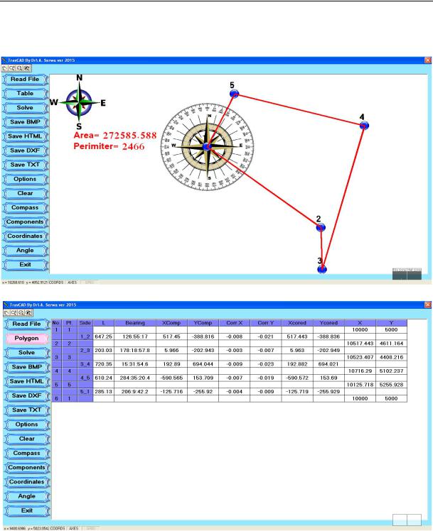
3 –– Main form: Contains functions commands to the left, CAD module (Figure 6a) and calculations table (Figure 6b).
Fig. 6: a) Main form with CAD module, b) Main form with calculation table
Some advanced tasks can be found in the main form such as:
––Read traverse file.
––Show polygon (1:1 scale)
––Show calculation table.
––Solve (apply all steps of traverse computations as mentioned in section (3-2).
46
Issue № 1(29), 2016 |
ISSN 2075-0811 |
––Save as BMP (save the traverse image as displayed).
––Save as HTML (save the traverse image and calculation table in HTML format in order to publish it on the web.
––Save DXF (export the traverse to the AutoCAD environment).
––Save as TXT (export the traverse final coordinates in ASCii format).
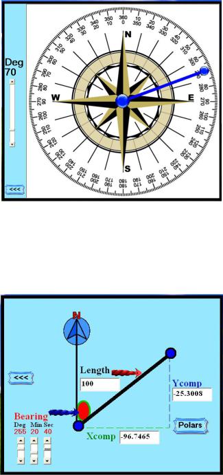
4 –– Compass form: it is a tutorial form to make the user familiar with WCB and directions as shown in Figure 7.
Fig. 7. Compass form
5 –– Components form: it is a calculator for departure and latitude from known length and WBC according to equation (6) and (7). The polar components (length and WBC) can also be computed as shown in Figure 8.
Fig. 8. Component form
47
Scientific Herald of the Voronezh State University of Architecture and Civil Engineering. Construction and Architecture
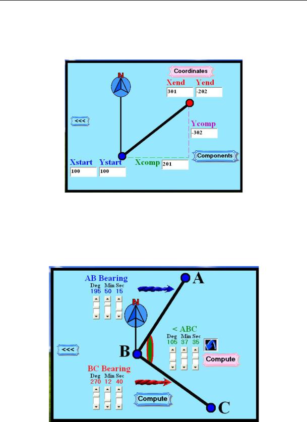
6 –– Coordinates form: it is a calculator for coordinates of points from known coordinates of previous point and the components of the containing line. Also it can calculate components of a line from coordinates of two belonging points as shown in Figure 9.
Fig. 9. Coordinates form
7 –– Angle form: it is a tutorial form that enables the engineer to understand and apply the relation between two lines and the angle in between according to equation (5) as shown in Figure 10.
Fig. 10. Angle form
8 –– CAD module: it contains additional tasks such as:
–– CAD interaction tasks such as zoom in, zoom out, zoom window, zoom previous and pan.
48
Issue № 1(29), 2016 |
ISSN 2075-0811 |
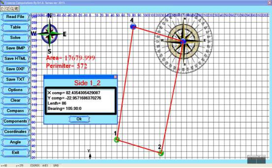
––Computing area and perimeter of the traverse.
––Display grid scale 1:1
––Display Compass on any traverse point. Most of these tasks shown in Figure 11.
Fig. 11. CAD Module
The software shall link with web using HTML output. Another privilege is CAD interface and output including: advanced zoom (in, out, window, extent and undo) in addition to DXF operations such as point extraction and output. With its name, it has a great privilege of CAD familiarity that eases of surveying drawings treatment. Zoom in, zoom out, zoom window and zoom previous for example makes the developed SW familiar to civil engineers. The compatibility between the developed SW and AutoCAD is a strong point to allow the user to store and retrieve data between the two SW. File processing between TravCAD and AutoCAD can be expressed in DXF file conversion. TravCAD can convert point ASCii format to DXF format in order to display the adjusted traverse in AutoCAD to continue surveying work. The last notice is that the first author has the only commercial rights concerned with TravCAD.
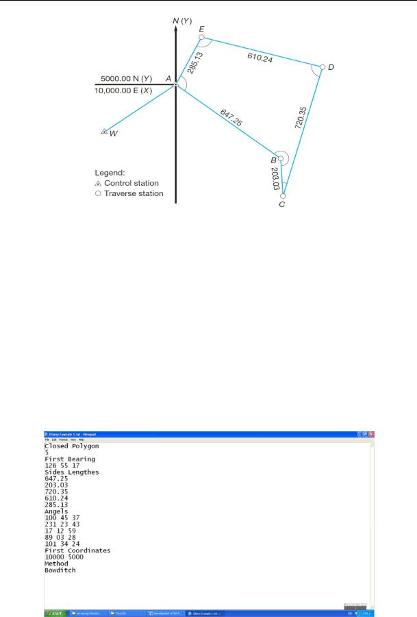
4 –– Application: In order to proof TravCAD reliability an example of textbook of "Elementary Surveying –– An Introduction to Geomatics 13th ed –– E. Ghilani, P. Wolf" were adopted as follow: The given example can be shown in Figure 12.
49
Scientific Herald of the Voronezh State University of Architecture and Civil Engineering. Construction and Architecture
Fig. 12. Example of closed polygon traverse [after Ghilani & Wolf, 2012]
The TravCAD file format including the given data and the method of adjustment can be indicated in Figure 13. TravCAD file formats differ according to the first line of the file (the type of the traverse). The format of closed polygon file is as following:
––Type of the traverse.
––Number of sides.
––WBC of starting side.
––Side lengths.
––Internal angles.
––Coordinate of starting point.
––Adjustment method.
Fig. 13. TravCAD format file for closed polygon traverse
50