Материал: Крючков Фундаменталс оф Нуцлеар Материалс Пхысицал Протецтион 2011


Внимание! Если размещение файла нарушает Ваши авторские права, то обязательно сообщите нам

assessments, access control, control panels and so on), the structure and composition of physical barriers (perimeter, onsite, buildings and rooms) and tactics of the response force. The efficiency of the options is assessed, and the materials and workforce needed to implement these are identified.

The site security service examines the options and chooses the most feasible one. This takes into account not only the efficiency and the cost of the option in question but also practical considerations relating to the NI operations (installation retrofit plan, etc.).

The scope of the work for the most complex PPS creation phases (NI vulnerability analysis and PPS efficiency assessment) is considered below. A note should be made that a vulnerability analysis should be conducted on a periodic basis to track down potential changes in threats, intruder models, onsite NM configurations and the PPS structure and composition. The PPS efficiency is subject to assessment not only at the predesign stage but at all subsequent stages as well, including during the PPS operations following the commissioning.

456

CHAPTER 7

NI VULNERABILITY ANALYSIS

A vulnerability analysis shall be performed early into the predesign stage and include, primarily, determination of the external and internal threats the installation may be exposed to and the vulnerability areas to be subject to physical protection.

The NI vulnerability analysis results are taken as the input for the NI conceptual design.

The key phases of a vulnerability analysis are:

∙formation of an expert team to conduct the analysis;

∙development of the analysis program;

∙acquisition of initial data on the NI vulnerabilities and the items to be subject to physical protection;

∙determination of threats and attacker models;

∙finalization of the analysis results.

As defined by the “Physical Protection Rules ...”, a vulnerability analysis is undertaken by the NI administration involving, where required, specialized organizations (security agencies, research and design organizations specializing in the field of the given NI, etc.).

Determination of the NF vulnerability areas is the process of identifying the NF elements that may be potential targets of an attacker and the locations thereof.

In terms of NM thefts, the NI vulnerabilities are locations within the guarded areas where NM is stored or used.

NM-related vulnerabilities are more apparent. These are NM locations. Identifying vulnerabilities of an NF requires a special analytical work. For example, the answer to the question if failure (collapse) of an NF component (pump, vessel, pipeline, control system cable, etc.) leads to severe radiological effects is not altogether obvious and needs rather indepth studies, NF simulations and so on.

The NF vulnerabilities may be identified using logic schemes and the mathematical graph-theory apparatus.

A logic scheme is an efficient tool of identifying vulnerabilities when considering potential threats of NM theft or acts of sabotage at the NF.

Let us consider an example of a hazardous aftermath (event), i.e. radioactivity escape as the result of an act of sabotage with respect to a component of a WWER-type reactor.

457

Normally, for an analysis, a tree of failures from sabotage (TFS) is built (Fig. 7.1).

It can be seen from Fig. 7.1 that the end event “Ra dioactivity escape” is expanded into intermediate events of level 1, level 2 and so on until we arrive at the initial events. Fig. 7.2 gives an example of the event “Escape during power operation” (level 3) expanded into 3 m ore levels.


Radioactivity escape


Утечка радиоактивности


на ВВЭР


from WWER reactor


УРВВЭР


REWWER

I


Утечка из системы


Утечка из системы

Escape from the fresh or


УтечкаEscapeизfromкорпусаthe


Escape from the RW

хранения свежего или


хранения радиоактивных

spent fuel storage system


активной зоны


storage system

отработавшего топлива


core vessel


отходов


ECV


EFS


УКАЗ


ERWS


УХТ


I


УХРО


EscapeУтечкаduringво времяreactor


УтечкаEscapeвоduringвремя


Утечка во время работы


Escape during

остановки реактора


перегрузки топлива


на мощности

shutdown


refueling


power operation

УВОР


УВПТ


УВРМ

EDRS


EDF


EDPO

Fig. 7.1. Upper part of the TFS for WWER reactor

458

EFC


Escape during power


operation


EDPO

I


Escape during core


Escape without core


melting


melting


EDCM


EWCM


&


Reactor containment


Fuel element cladding


Failure of the primary


failure from fuel


failure


circuit boundary


melting


RCF

FCFFM


FPCB

I


Fuel melting as the result of


Fuel melting as the result of


Fuel melting as the result

loss-of-coolant


loss-of-coolant


of an operational

accident with


accident with


occurrence

insufficiency of


a failure of


with a failure of

safety


safety


safety

systems


systems


systems


FM-LCISS

FM-LCFSS


FM-OOFSS

Fig. 7.2. Expansion of a level 3 event (Note: EFC – escape from core)

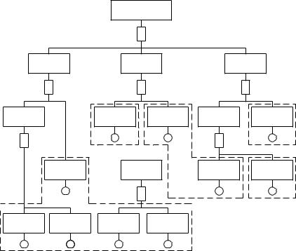
The next step in defining the protected area is to locate the NF component which, if failed, may induce the given event. To do this, the tree of events (Fig. 7.3) should be transformed into a tree of locations.

459
Radioactivity escape in escape of permissible level

RE

I

Intermediate


Intermediate


Intermediate


event 1


event 2


event 3

IE1

I


IE2


IE3


&


&

Intermediate


Initial

Initial

Intermediate

Initial

event 4


event 6

event 7

event 6

event 10

IE4


E6

E7


IE6

E10

&


L2


&

L4


Initial


Intermediate


Initial

Initial


event 3


event 5


event 8

event 9


E3


IE5


E8

E9


I


L3

L5

Initial

Initial


Initial

Initial


event 1

event 2


event 4

event 5


E1

ES2

E4

E5


L1


Fig. 7.3. Example of an event tree

Let us assume that the locations L1…L5 match the in itial events E1…E10.

460

Источник: https://studfile.net/preview/16708779/