Материал: m013802e_a
2.2.2 Supply voltage of the field side
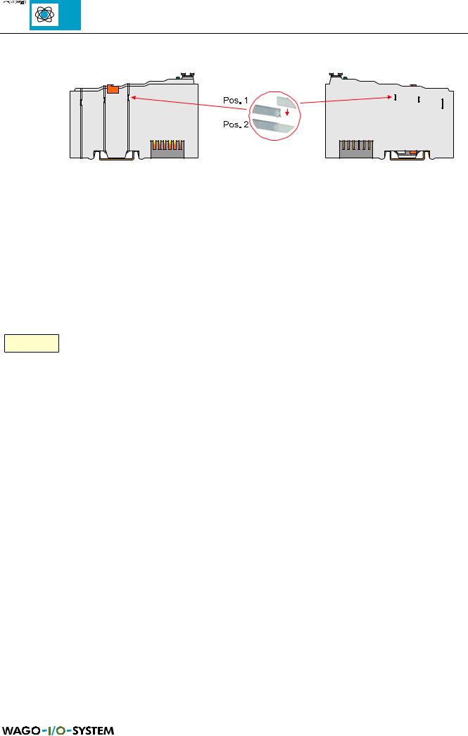
Fig. 2.4: Power contact for the power supply to the field side
The power is supplied to the field side automatically by snap-fitting the individual I/O modules via self-cleaning power contacts (Fig. 2.4). These contacts are arranged on the right hand side of the coupler/controller and the I/O modules, protected against accidental contact, as spring contacts. On the left hand side of the I/O modules are corresponding male contacts as counter pieces. Ensure that the current of the power contacts does not permanently exceed 10 A.
The PE contact is a preceding ground (earth) contact corresponding to the standards which can be used as a protective earth. The contact has a leakage capacity of 125 A.
яюэьыъщэш Please note that some I/O modules do not have any, or only individual power contacts (dependent of the I/O function). This configuration is intended to interrupt the power supply. If a field supply is required for the following I/O modules, it is necessary to use a power supply module. Take note of the individual terminal/module data sheets! The design of some modules does not physically allow assembly them in rows as the grooves for the male contacts are closed at the top.
By fitting an additional power supply module the field supply is always interrupted by the power contacts. From this point a new power supply is made, which can also include a potential change (see Fig. 2.2). This possibility guarantees a high degree of system flexibility.
12 |
MODBUS / Coupler/controller |
15.12.99
2.3 Station address
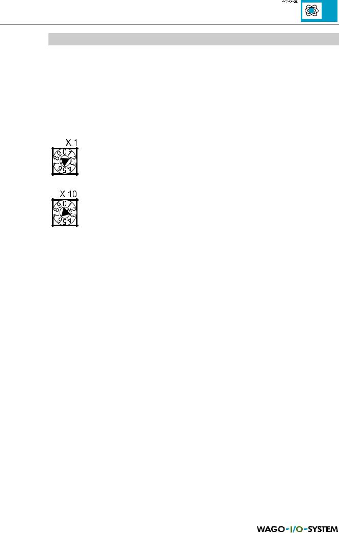
The station address is set using both coding switches. The settable address is within the 01 and 99 range. The value 00 is reserved for the programming and configuration mode.
The lower coding switch serves for setting the address tens digit, the upper coding switch for setting the units digit. The address is only read in and saved when switching on. Changes made during operation have no effect.
The following example shows the setting of address 62:
Fig. 2.5: Coding switch
MODBUS / Coupler/controller |
13 |
15.12.99
2.4 Mode switch
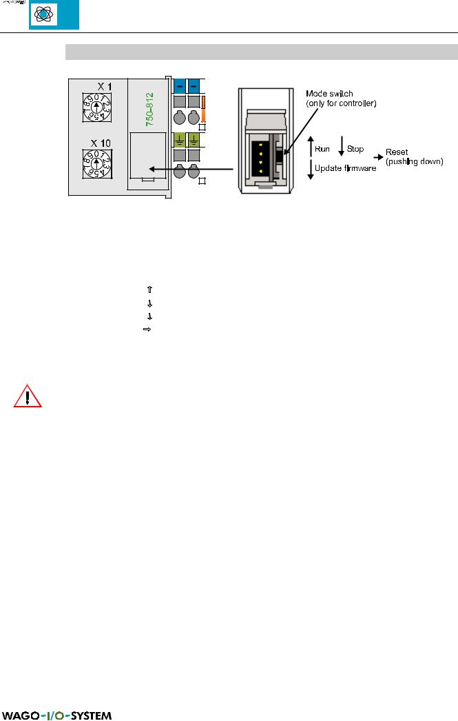
Fig. 2.6: Mode switch
The mode switch is only available in the controller and permits a manual Run/Stop- status change.
Mode switch setting |
Function |
From Stop to Run: |
Activate program processing |
From Run to Stop: |
Stop program processing |
(Bootstrap:) |
To bootstrap the firmware, not required by user |
Hardware reset: |
Mode switch e.g. push down with screwdriver |
|
All outputs are reset, variables are set to 0 or FALSE or to their initial value. |
|
Flags remain in the same status. |
|
Reset can be made with both Stop as well as Run. |
Table 2.1: Mode switch, controller |
Stop = Program processing stopped |
|
Run = Program processing running |
ATTENTION!
If when changing over the mode switch from ‘Run’ to ‘Stop’ outputs are still activated, these will remain in this status! Switching off on the software side, e.g. by initiators is then ineffective because the program will no longer be processed!
(A mode change over is made internally at the end of a program cycle‘.)
14 |
MODBUS / Coupler/controller |
15.12.99
2.5 Fieldbus connection
2.5.1 RS 485
Coupler : 750-312 and 750-315
Controller: 750-812 and 750-815
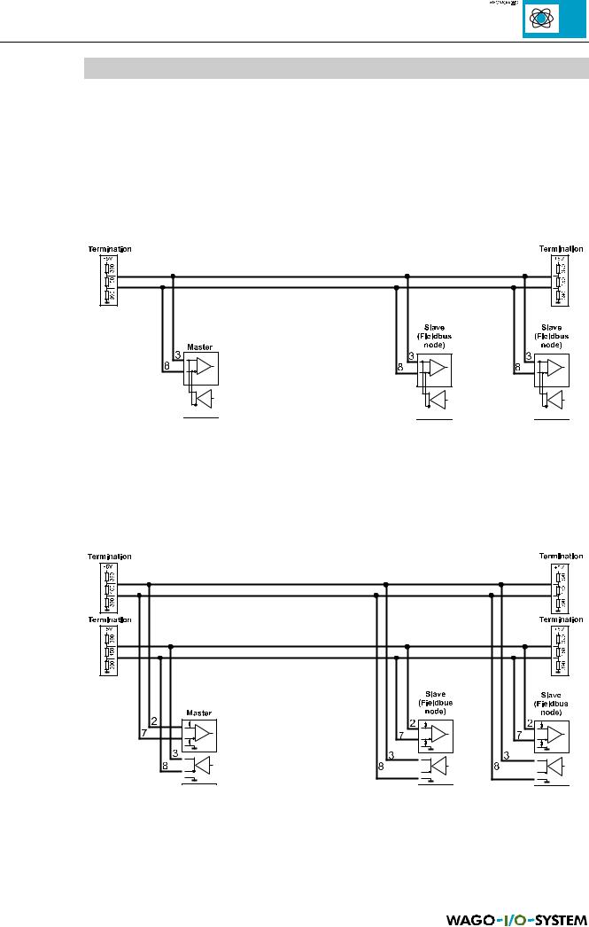
One transmission medium for the MODBUS is RS485, whereby, 2 or 4 wire can be used. The following figure shows an example for a 2 wire version:
Fig. 2.7: 2 wire connection
As opposed to the above the 4 wire connection offers the advantage that it can use simpler repeaters and converter. The following illustration is a corresponding example:
Fig. 2.8: 4 wire connection
MODBUS / Coupler/controller |
15 |
15.12.99

Connect the D-SUB connection plug as follows:
9 pol. D-SUB |
Signal |
Direction |
Description |
1 |
- |
|
not used |
2 |
RxD |
In |
Signal received (4 wire) |
3 |
TxD (RxD) |
Out |
Signal transmitted (received) (2 wire) |
4 |
DE |
Out |
Repeater control signal |
5 |
GND |
PWR |
Signal and supply earth (ground) |
6 |
Vcc |
PWR |
Supply voltage, +5V (only for external connections) |
7 |
RxD inverted |
In |
Receive signal with inverted level (4 wire) |
8 |
TxD (RxD) inverted |
Out |
Send signal with inverted level (receive) (2 wire) |
9 |
- |
|
not used |
Table 2.2: Pin assignment for 4 wire connections
The connection point is mechanically lowered so that fitting into a 80 mm deep switch cabinet is possible following the plug-in connection.
The pin assignment is 2 wire operation conforms with the Profibus assignment. Thus the Profibus wiring components can be used.
One application possibility is the connection of a Yokogawa Interface. This PCB supports the MODBUS protocol. The standard setting is the RTU mode (see chapter MODBUS) and 4 wire connections. The pin assignment is as follows:
9 pol. D-SUB |
Signal |
25 pol. SUB D |
Signal |
Colour |
1 |
- |
- |
- |
- |
2 |
RxD |
14 |
SD A |
brown |
3 |
TxD (RxD) |
16 |
RD A |
red |
4 |
DE |
- |
- |
- |
5 |
GND |
25 |
SG |
yellow/black |
6 |
Vcc |
- |
- |
- |
7 |
RxD (inv) |
18 |
SD B |
black (brown pair) |
8 |
TxD(RxD) (inv) |
19 |
RD B |
black (red pair) |
9 |
- |
- |
- |
- |
Table 2.3: Yokogawa interface pin assignment
Switches for RS 485
The setting for 2 or 4 wire connections and switching in or out of the corresponding matching resistors is made by switches, covered by the enclosure. To access the switches remove the enclosure from the coupler/controller. A protruding locking device can be found on the bottom of the unit on the two short sides. Push the two short sides apart to permit the enclosure to be pushed past the unit metal plate. Simultaneously press from above on the right hand section of the coupler/controller, which is the supply side.
16 |
MODBUS / Coupler/controller |
15.12.99