Материал: m013802e_a
The enclosure prevents unintentional changes of the settings during later operation. If, however, access to the settings is required in the case of a fault, ensure that the previous settings are marked on a label.
After changing the settings push the enclosure back onto the coupler/controller. Note that it may be necessary to lightly push the wide side of the coupler/controllers to the side when the metal plate does not easily slide into the enclosure. In addition it may be necessary to push the rotary switches into the cut-outs provided.
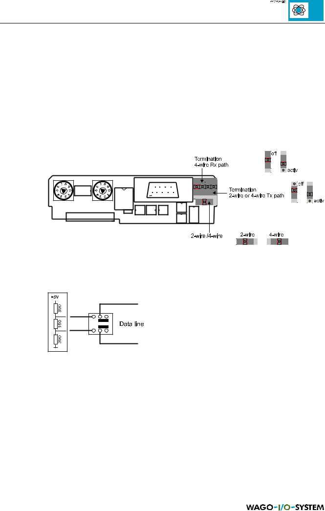
The switch on the interface printed circuit board for setting 2 and 4 wire connections or for the matching resistors can be found in the following illustration:
Fig. 2.9: Interface printed circuit board
For 2 wire connections RxD and TxD are short circuited. By the termination, a series circuit comprising of 3 resistors is connected to the bus conductor terminations.
Fig. 2.10: Internal matching resistors and interface switches
The standard setting for the supplied coupler/controller is a 2 wire connection and a switched off matching resistor.
Four wire connections can be terminated as well as the receiver line.
MODBUS / Coupler/controller |
17 |
15.12.99
2.5.2 RS 232
Coupler : 750-314 and 750-316
Controller: 750-814 and 750-816
The MODBUS can also be operated directly on an RS 232 interface. The D-SUB connection plug is connected in this case as follows:
9-pol. D-SUB |
Signal |
Direction |
Description |
1 |
- |
|
not used |
2 |
TxD |
Out |
Signal received |
3 |
RxD |
In |
Signal transmitted |
4 |
- |
|
not used |
5 |
GND |
PWR |
Signal and supply earth (ground) |
6 |
- |
|
not used |
7 |
- |
|
not used |
8 |
- |
|
not used |
9 |
- |
|
not used |
Table 2.4: RS 232 plug assignment
The pin assignment permits the use of commercially available 9 pole 1:1 sockets/ plug lines for direct connection to a PC.
18 |
MODBUS / Coupler/controller |
15.12.99
3 Technical Data
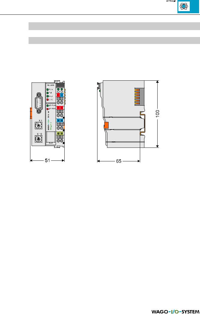
3.1 Dimensions
Fig. 3.1: Dimensions of coupler/controller
MODBUS / Technical data |
19 |
15.12.99
3.2 Coupler
SYSTEM DATA:
|
750-312 |
750-315 |
750-314 |
|
750-316 |
|
|
|
|
|
|
Max. number of nodes |
99 with repeater |
|
1 |
||
Max. number of I/O points |
about 6,000 (depends on master) |
256 |
|||
Transmission medium |
|
Shielded Cu cable 2 (4) x 0.25 mm² |
|
|
|
Max. length of bus line |
1,200 m (depends on baud rate/on the |
about 5 m |
|||
Baud rate |
150-19,200 bauds |
1.2-115.2 kbauds |
150-19,200 bauds |
|
1.2-115.2 kbauds |
Type of transmission |
RS 485 |
RS 232 |
|||
Table 3.1: System data, coupler |
|
|
|
|
|
TECHNICAL DATA:
|
750-312, 750-314, 750-315, 750-316 |
|
|
Max. number of I/O modules |
64 |
Digital points per node |
256 (inputs and outputs) |
Analogue points per node |
128 (inputs and outputs) |
Configuration possibility |
DIP switch and decimal coder |
|
via PC or PLC device |
Bus coupler connection |
1 x D-Sub 9 |
Voltage supply |
24 V DC (-15%/+20%) |
Internal current consumption |
350 mA |
Current supply |
85 mA typ. |
|
580 mA max. |
Power jumper contacts |
Blade / spring contact, |
|
slide contacts, self-cleaning |
Voltage power jumper contacts |
24 V DC |
Current power jumper contacts |
10 A DC |
Max. current supply at intern. |
1,65 A |
Data contacts |
Slide contacts, 2,5ÿ hart gold-plated |
|
self-cleaning |
Housing material |
Polycarbonate, polyamide 6.6 |
Marking |
Standard marker cards WAGO BR247/278 |
|
Marking cards 8 x 47 mm |
Wire connection |
CAGE CLAMP, 0.08 mm² - 2.5 mm² |
Vibrations-/Schockfestigkeit |
IEC 68-2-6 / IEC 68-2-27 |
Fitting position |
any |
System of protection |
IP 20 |
Insulation |
500 V system/supply |
Operating temperature |
0 °C ... +55 °C |
Dimensions in mm |
51 x 65* x 100 (*from upper edge of DIN 35 rail) |
Table 3.2: Technical data, coupler |
|
20 |
MODBUS / Technische Daten |
15.12.99
3.3 Controller
SYSTEM DATA:
|
750-812 |
750-815 |
750-814 |
|
750-816 |
|
|
|
|
|
|
Max. number of nodes |
99 with repeater |
1 |
|
||
Max. number of I/O points |
about 6,000 (depends on master) |
256 |
|||
Transmission medium |
|
Shielded Cu cable 2 (4) x 0.25 mm² |
|
||
Max. length of bus line |
1,200 m (depends on baud rate/on the |
about 5 m |
|||
Baud rate |
150-19,200 bauds |
1.2-115.2 kbauds |
150-19,200 bauds |
|
1.2-115.2 kbauds |
Type of transmission |
RS 485 |
RS 232 |
|||
IEC 1131-3 programming |
|
WAGO-I/O-PRO |
IL, LL, FDB, ST, FC |
|
|
Table 3.3: System data, controller |
|
|
|
|
|
TECHNICAL DATA:
|
|
750-812, 750-814, 750-815, 750-816 |
|
|
|
|
Max. number of I/O modules |
64 |
|
Digital points per node |
256 (inputs and outputs) |
|
Analogue points per node |
128 (inputs and outputs) |
|
Configuration possibility |
With function modules and switches |
|
Program memory |
32 kbytes |
|
Data memory |
32 kbytes |
|
Residual memory |
8 kbytes (retain) |
|
I/O fieldbus area |
256 words in input area and 256 words in output area |
|
I/O modules area |
256 words for inputs and 256 words for outputs |
|
Cycle time |
< 3 ms for 1,000 statements / 256 I/O |
|
Bus coupler connection |
1 x D-Sub 9 |
|
Voltage supply |
24 V DC (-15%/+20%) |
|
Internal current consumption |
350 mA |
|
Current supply |
85 mA typ. |
|
|
580 mA max. |
|
Power jumper contacts |
Blade / spring contact, |
|
|
slide contacts, self-cleaning |
|
Voltage power jumper contacts |
24 V DC |
|
Current power jumper contacts |
10 A DC |
|
Max. current supply at intern. |
1.65 A |
|
Data contacts |
Slide contacts, 2.5ÿ hart gold-plated |
|
|
self-cleaning |
|
Housing material |
Polycarbonate, polyamide 6.6 |
|
Marking |
Standard marker cards WAGO BR247/278 |
|
|
Marking cards 8 x 47 mm |
|
Wire connection |
CAGE CLAMP, 0.08 mm² - 2.5 mm² |
|
Resistance to shocks/vibrations |
IEC 68-2-6 / IEC 68-2-27 |
|
Fitting position |
any |
|
System of protection |
IP 20 |
|
Insulation |
500 V system/supply |
|
Operating temperature |
0 °C ... +55 °C |
|
Dimensions in mm |
51 x 65* x 100 (*from upper edge of DIN 35 rail) |
|
Table 3.4: Technical data, controller |
|
MODBUS / Technical data |
21 |
|
15.12.99