Материал: m083300e
Fieldbus coupler / controller |
• 77 |
Fieldbus Controller 750-833 |
|
|
|
3.2.2Hardware
3.2.2.1View
|
|
|
|
PROFIBUS |
01 |
02 |
|
|
|
|
RUN |
A |
|
|
|
|
|
|
|
|
|
|
|
|
|
|
C |
|
|
|
|
BF |
B |
|
|
|
|
|
|
D |
|
|
|
|
|
|
|
|
|
|
|
|
DIA |
24V |
0V |
|
|
|
|
|
||
Feldbus- |
|
|
|
BUS |
|
|
|
|
|
|
|
|
|
anschluss |
|
|
|
|
|
|
D-Sub |
|
|
|
I/O |
+ |
+ |
|
|
|
|
USR |
||
|
|
|
|
|
|
|
|
ADDRESS |
|
|
|
||
|
|
|
x1 |
|
- |
- |
|
901 |
|
|
|
||
Adresse |
8 |
|
4 |
833 |
|
|
7 |
|
|
|
|||
|
3 |
|
|
|
||
|
|
|
2 |
|
|
|
|
6 |
|
- |
|
|
|
|
|
5 |
750 |
|
|
|
|
|
|
|
|
|
|
|
|
|
x10 |
|
PE |
PE |
|
|
|
|
|
|
|
|
901 |
|
|
|
||
Adresse |
8 |
|
3 |
|
|
|
7 |
|
|
|
|
||
|
|
|
2 |
|
|
|
|
6 |
4 |
|
|
|
|
|
|
5 |
|
|
|
|
Konfigurations- |
|
|
|
|
|
|
und Programmier- |
|
|
|
|
|
|
Schnittstelle |
|
|
|
|
|
|
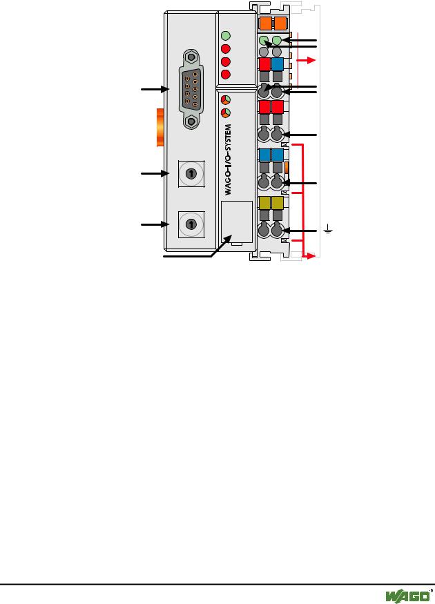
Fig. 3-12: Fieldbus coupler 750-833 PROFIBUS DP/V1
Status der Betriebsspannung -Leistungskontakte -System
Datenkontakte
Versorgung 24V
0V
Versorgung über Leistungskontakte 24V
0V
Leistungskontakte
g083300d
The controller comprises of:
•Device supply with internal system supply module for the system supply as well as power jumper contacts for the field supply via assembled I/O modules
•Fieldbus interface with the bus connection
•2 rotary switches for the station address (decimal)
•Display elements (LED's) for status display of the operation, the bus communication, the operating voltages as well as for fault messages and diagnosis
•Configuration and programming interface
•Operating mode switch
•Electronics for communication with the I/O modules (internal bus) and the fieldbus interface
WAGO-I/O-SYSTEM 750 |
D R A F T |
PROFIBUS |
2001-02-27 |
78 • Fieldbus coupler / controller
Fieldbus Controller 750-833
3.2.2.2Device supply
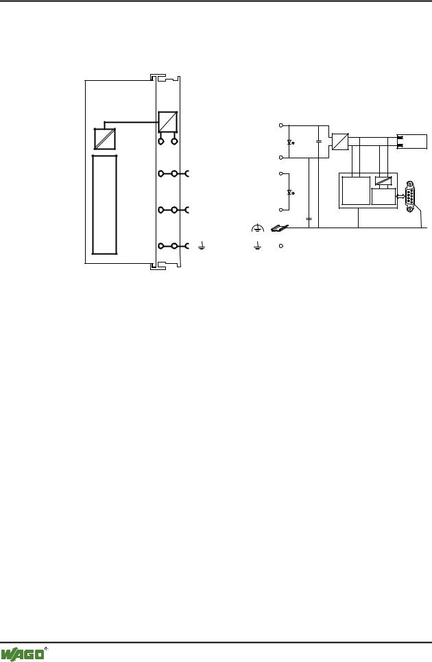
The supply is via fed in via terminal blocks with CAGE CLAMP® connection. Device supply is intended for system supply and field side supply.
|
|
|
|
|
|
|
|
FELDBUSNTEIRFACE |
ELEKTRONIK |
||
|
|
|
|
|
|
24V |
|
1 |
5 |
DC |
Bus- |
|
24V/0V |
||
|
10nF |
klemmen |
|
|
|
DC |
|
|
|
0V |
|
2 |
6 |
|
|
|
24V |
24V |
|
|
|
ELEKTRONIK |
FELDBUS |
|
|
|
|
|
|
|
INTERFACE |
3 |
7 |
|
|
|
0V |
0V |
|
10nF
4 8
750-333
Fig. 3-13: Device supply |
g012105d |
The integrated internal system supply module generates the necessary voltage to supply the electronics and the connected I/O modules.
The fieldbus interface is supplied with electrically isolated voltage from the internal system supply module.
D R A F T |
WAGO-I/O-SYSTEM 750 |
2001-02-27 |
PROFIBUS |
Fieldbus coupler / controller |
• 79 |
Fieldbus Controller 750-833 |
|
|
|
3.2.2.3Fieldbus connection
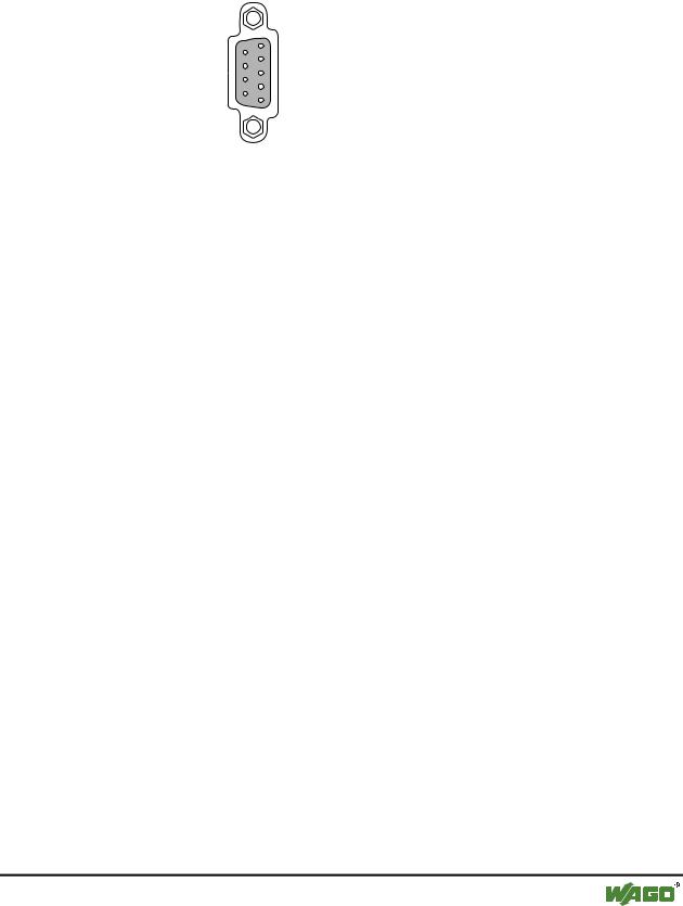
The PROFIBUS interface is designed as a Sub-D connection in accordance with the US Standard EIA RS 485 for cable linked data transmission.
9-pol. D-Sub-Buchse
|
5 |
DGND |
|
9 |
RTS |
RxD/TxD-N |
4 |
|
8 |
RxD/TxD-P |
|
|
3 |
|
|
7 |
|
VP |
2 |
|
6 |
|
|
|
1 |
|
Fig. 3-14: Bus connection, D-SUB |
g012102d |
||
|
|
|
|
|
Pin |
Signal |
Description |
|
3 |
RxD(TxD)-P |
Transmit (receive) signal |
|
|
|
|
|
4 |
RTS |
Ready To Send |
|
|
|
|
|
5 |
GND |
Supply ground |
|
|
|
|
|
6 |
Vcc |
Supply voltage |
|
|
|
|
|
8 |
RxD(TxD) N |
Transmit (receive) signal |
|
|
|
|
The connection point is mechanically lowered permitting fitting in an 80 mm high switch box once connected
WAGO-I/O-SYSTEM 750 |
D R A F T |
PROFIBUS |
2001-02-27 |
80 • Fieldbus coupler / controller
Fieldbus Controller 750-833
3.2.2.4Display elements
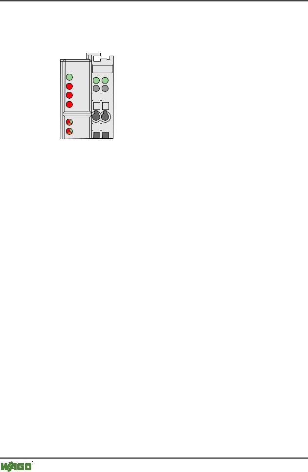
The operating status of the fieldbus coupler or of the node is signalled via light diodes (LED).
|
PROFIBUS |
|
|
|
|
|
|
|
|
|
|
|
|
|
|
|
|
|
|
|
|
|
|
|
|
|
|
|
|
|
|
|
|
RUN |
A |
|
|
|
|
|
|
||
|
|
|
|
|
|
C |
|
|
||
|
BF |
B |
|
|
|
|
|
|
||
|
|
|
|
|
D |
|
|
|||
|
|
|
|
|
|
|
|
|||
|
DIA |
24V |
|
0V |
|
|
|
|
|
|
|
|
|
|
|
|
|||||
|
BUS |
|
|
|
|
|
|
|
|
|
|
|
|
|
|
|
|
|
|
|
|
|
I/O |
|
|
|
|
|
|
|
|
|
+ |
|
+ |
|
|
|
|
|
|||
|
USR |
|
|
|
|
|
|
|||
|
|
|
|
|
|
|
|
|
|
|
Fig. 3-15: Display elements 750-833 |
g012107x |
|||||||||
|
|
|
|
|
|
|||||
|
LED |
|
Colour |
Meaning |
|
|||||
|
RUN |
|
green |
The 'RUN' LED indicates to the user whether the fieldbus coupler / |
||||||
|
|
|
|
|
|
|
|
|
controller is correctly initialised. |
|
|
|
|
|
|
|
|||||
|
BF |
|
red |
The 'BF' LED indicates whether the communication via the |
|
|||||
|
|
|
|
|
|
|
|
|
PROFIBUS is functioning. |
|
|
|
|
|
|
||||||
|
DIA |
|
red |
The 'DIA' LED indicates an external diagnosis. The signalling is not |
||||||
|
|
|
|
|
|
|
|
|
supported by all devices. |
|
|
|
|
|
|
|
|||||
|
BUS |
|
red |
The 'BUS' LED signalled a projecting fault. |
|
|||||
|
|
|
|
|
||||||
|
IO |
|
red /green |
The 'I/O' LED indicates the operation of the node an and signals |
||||||
|
|
|
/ orange |
faults occurring. |
|
|||||
|
|
|
|
|
||||||
|
USR |
|
red /green |
The 'USR' LED can be selected by a user program in a programma- |
||||||
|
|
|
/ orange |
ble fieldbus controller. |
|
|||||
|
|
|
|
|
|
|||||
|
A |
|
green |
Status of the operating voltage – system |
|
|||||
|
|
|
|
|
|
|||||
|
C |
|
green |
Status of the operating voltage – power jumper contact |
|
|||||
|
|
|
|
|
|
|
|
|
|
|
D R A F T |
WAGO-I/O-SYSTEM 750 |
2001-02-27 |
PROFIBUS |
Fieldbus coupler / controller |
• 81 |
Fieldbus Controller 750-833 |
|
|
|
3.2.2.5Station address
The station address is determined via two decimal rotary switches on the electronic module.
ADDRESS x1
|
901 |
|
|
|||
|
8 |
|
|
2 |
|
|
|
7 |
|
3 |
|
|
|
|
|
6 |
4 |
|
|
|
|
|
|
|
|
||
|
|
|
5 |
|
|
|
|
|
|
|
x10 |
|
|
|
901 |
|
|
|||
|
8 |
|
|
2 |
|
|
|
7 |
|
3 |
|
|
|
|
|
6 |
4 |
|
|
|
|
|
|
|
|
||
|
|
|
5 |
|
|
|
Fig. 3-16: Creating the station address |
g012102d |
|||||
The switch „x1“ determines the unit position of the address. The switch „x10“ determines the tens position of the address. Valid station addresses lie between 1 and 99.
The station address is taken over by the fieldbus coupler after switching on the device (initialisation phase). Adjustments to the switch during operation have no effect.
Note
After Power-On the station address 0 causes the run-up of the controller and start of the PLC functions, without the fieldbus being active.
Using this function an autarcic small scale control can be realised using the WAGO-I/O-SYSTEM 750
3.2.2.6Configuration and programming interface
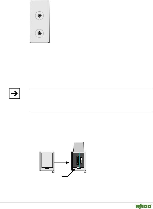
The configuration and programming interface is located behind the cover flap. This is used to communicate with WAGO-I/O-CHECK and WAGO-I/O-PRO as well as for firmware uploading.
Konfigurationsund
Programmierschnittstelle
Fig. 3-17: Configuration interface |
g01xx07d |
The communication cable (750-920) is connected to the 4 pole male header.
WAGO-I/O-SYSTEM 750 |
D R A F T |
PROFIBUS |
2001-02-27 |