Материал: m083300e

122 • Fieldbus coupler / controller
Fieldbus Controller 750-833
3.2.9.6.2I/O modules fault cases
Article number |
Channel |
Fault type |
Meaning |
|
type |
||||
|
|
|
||
750-418, 750-419, |
'001 |
0.1001' |
Fault (line break, overload or short |
|
750-507, 750-522 |
|
|
circuit) |
|
|
|
|
|
|
750-506 |
'001 |
0.0001' |
Short circuit |
|
|
|
0.0010' |
Lower voltage |
|
|
|
0.0110' |
Line break |
|
|
|
0.1001' |
Error |
|
|
|
|
|
|
750-461, 750-469 |
'101 |
0.0110' |
Line break |
|
|
|
0.1000' |
Lower limit value gone below |
|
|
|
1.0000' |
Parameterisation fault |
|
|
|
1.1111' |
I/O module fault |
|
|
|
|
|
|
750-462, 750-465, |
'101 |
0.0111' |
Lower limit value gone below |
|
750-466, 750-472, |
|
0.1000' |
Upper limit value exceeded |
|
750-474, 750-479, |
|
1.0000' |
Parameterisation fault |
|
750-480 |
|
1.1111' |
I/O module fault |
|
|
|
|
|
|
750-610, 750-611, |
'001 |
1.0001' |
Field voltage fault |
|
|
|
1.0010' |
Fuse fault |
|
|
|
|
|
|
750-630 |
'110 |
1.1010' |
SSI_IN fault (external fault) |
|
|
|
1.1011' |
SSI FRAME fault |
|
|
|
1.0000' |
Parameterisation fault |
|
|
|
1.1111' |
I/O module fault |
|
|
|
|
|
|
750-635, 750-637 |
'110 |
0.1001' |
Error |
|
|
|
1.0000' |
Parameterisation fault |
|
|
|
1.1111' |
I/O module fault |
|
|
|
|
|
|
750-650, 750-651, |
'110 |
0.1001' |
Buffer overflow |
|
750-653, 750-654 |
('000) |
1.0000' |
Parameterisation fault |
|
|
|
1.1111' |
I/O module fault |
|
|
|
|
|
D R A F T |
WAGO-I/O-SYSTEM 750 |
2001-02-27 |
PROFIBUS |

Fieldbus coupler / controller • 123
Fieldbus Controller 750-833
3.2.10Commissioning (start-up) with WAGO-I/O-PRO
in preparation
WAGO-I/O-SYSTEM 750 |
D R A F T |
PROFIBUS |
2001-02-27 |
124 • Fieldbus coupler / controller
Fieldbus Controller 750-833
3.2.11LED signalling
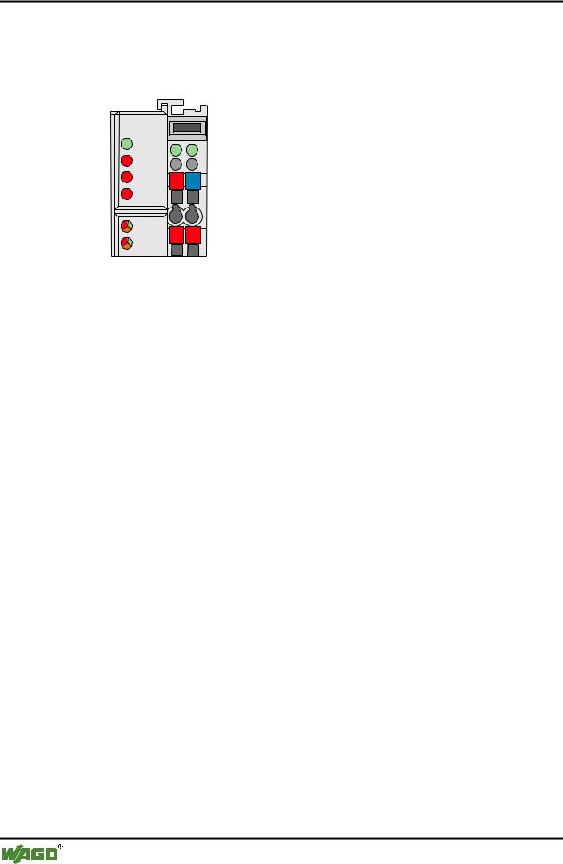
For the on-site diagnosis the controller has several LED´s, which display the operating status of the controller or the complete node.
PROFIBUS |
|
|
|
RUN |
A |
|
|
|
|
|
|
|
|
C |
|
BF |
B |
|
|
|
D |
|
|
|
|
|
|
DIA |
24V |
0V |
|
|
|
||
BUS |
|
|
|
I/O |
+ |
+ |
|
USR |
|
||
|
|
|
|
Fig. 3-22: Display element 750-833 |
g012107x |
||
3.2.11.1Blink code
A blink code displays detailed fault messages. A fault is cyclically displayed using up to 3 different blink sequences.
•The first blink sequence (approx. 10 Hz) indicates the fault display.
•After a pause a second blink sequence appears (approx. 1 Hz). The number of blink impulses gives the fault code.
•The third blink sequence (approx. 1 Hz) appears following a further pause. The number of blink pulses indicates the fault argument.
D R A F T |
WAGO-I/O-SYSTEM 750 |
2001-02-27 |
PROFIBUS |

Fieldbus coupler / controller • 125
Fieldbus Controller 750-833
3.2.11.2Fieldbus status
The upper four LED´s signal the operating status of the PROFIBUS communication.
LED |
Colour |
Meaning |
RUN |
green |
The 'RUN' LED shows the user whether the fieldbus controller is |
|
|
functioning correctly. |
|
|
|
BF |
red |
The 'BF' LED indicates whether the communication is functioning |
|
|
via the PROFIBUS. |
|
|
|
DIA |
red |
The 'DIA' LED indicates an external diagnosis. |
|
|
|
BUS |
red |
The 'BUS' LED signals a projecting fault. |
|
|
|
RUN |
BF |
DIA |
BUS |
Meaning |
off |
off |
off |
off |
The controller is not supplied with operating volt- |
|
|
|
|
age (Status LED of the bus controller does not light |
|
|
|
|
up) or a hardware fault exists. |
|
|
|
|
|
on |
on |
* |
off |
PROFIBUS interface started, baud rate not yet |
|
|
|
|
recognised. |
|
|
|
|
|
on |
blinks |
* |
off |
Baud rate recognised, station is not yet parameter- |
|
|
|
|
ised and configured. |
|
|
|
|
|
on |
blinks |
on |
blinks |
Slave was incorrectly projected. |
|
|
|
cycli- |
Fault message via a blink code |
|
|
|
cally |
|
|
|
|
|
|
on |
off |
* |
off |
The controller is exchanging data. |
|
|
|
|
|
on |
* |
on |
* |
The controller signals a pending diagnosis. |
|
* Not relevant |
|
|
|
WAGO-I/O-SYSTEM 750 |
D R A F T |
PROFIBUS |
2001-02-27 |

126 • Fieldbus coupler / controller
Fieldbus Controller 750-833
3.2.11.3Fault message by means of blink code of the BUS-LED
Fault argument |
Fault description |
Fault code 1: Fault in parameterisation telegram |
|
1 |
insufficient parameterisation data |
|
|
2 |
excessive parameterisation data |
|
|
Fault code 2: Fault in parameterisation telegram |
|
n |
Parameterisation byte n is faulty |
|
|
Fault code 3: Fault in configuration telegram |
|
1 |
insufficient configuration data |
|
|
2 |
excessive configuration data |
|
|
Fault code 4: Fault in configuration telegram |
|
n |
Configuration byte (module) n is faulty |
|
|
Fault code 5: Faulty data length |
|
1 |
maximum input data length exceeded |
|
|
2 |
maximum output data length exceeded |
|
|
Fault code 6: Compilate buffer overflow |
|
1 |
Compilate buffer overflow for DP process image |
|
|
2 |
Compilate buffer overflow for PFC process image |
|
|
D R A F T |
WAGO-I/O-SYSTEM 750 |
2001-02-27 |
PROFIBUS |