Материал: m083300e
Fieldbus coupler / controller • 127
Fieldbus Controller 750-833
3.2.11.4Node status
The 'I/O' LED indicates the node operation and signals the occurrence of a fault.
I/O |
USR |
Meaning |
green |
* |
Data cycle on the internal bus |
|
|
|
off |
* |
No data cycle on the internal bus |
|
|
|
red |
on |
Bus controller is in bootstrap mode or hardware defect on the controller |
|
|
systems |
|
|
|
red |
* |
During start up: internal bus being initialised |
blinks |
|
During operation: general internal bus fault |
|
|
|
red |
* |
Fault message during internal bus reset and internal fault |
blinks |
|
|
|
|
|
orange |
* |
FLASH access to bus device firmware |
|
* Not relevant |
|
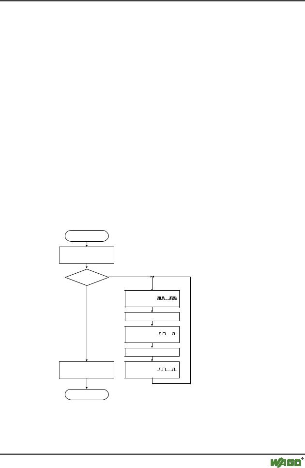
The controller starts up after switching on the supply voltage. The "I/O" LED blinks. The "I/O" LED has a steady light following a fault free run-up.
In the case of a fault the "I/O" LED continues blinking. The fault is cyclically displayed by the blink code.
Versorgungsspannung
einschalten
Koppler-Hochlauf
“I/O”-LED blinkt
Fehler |
Ja |
|
|
Nein |
|
“I/O”-LED
1. Blinksequenz
(leitet opt. Anzeige eines Fehlers ein)
1. Pause
“I/O”-LED
2. Blinksequenz
Fehlercode (Anzahl Blinkimpulse)
2. Pause
“I/O”-LED
“I/O”-LED an 3. Blinksequenz
Fehlerargument (Anz. Blinkimp.)
Feldbusstart |
|
Fig. 3-23: Signalling the LED node status |
g012111d |
After overcoming a fault restart the controller by switching off the supply voltage and then on again.
WAGO-I/O-SYSTEM 750 |
D R A F T |
PROFIBUS |
2001-02-27 |

128 • Fieldbus coupler / controller
Fieldbus Controller 750-833
3.2.11.5Fault message via blink code from the I/O-LED
Fault argument |
Fault description |
Fault code 1: Hardware and configuration fault |
|
0 |
EEPROM check sum fault / check sum fault in the parameter area of |
|
the flash memory |
|
|
1 |
Overflow of the internal buffer memory for the inline code |
|
|
2 |
Unknown data type |
|
|
3 |
Module type of the flash program memory could not be determined / |
|
is incorrect |
|
|
4 |
Fault when writing in the FLASH memory |
|
|
5 |
Fault when deleting the FLASH memory |
|
|
6 |
Changed I/O module configuration determined after AUTORESET |
|
|
7 |
Fault when writing in the serial EEPROM |
|
|
8 |
Invalid firmware |
|
|
Fault code 2: Fault in programmed configuration |
|
0 |
Incorrect table entry |
|
|
Fault code 3: Internal bus command fault |
|
0 |
Internal bus(es) has (have) identified internal bus commands as in- |
|
correct |
|
|
Fault code 4: Internal bus data fault |
|
0 |
Data fault on internal bus or |
|
Internal bus interruption on controller |
|
|
n* (n>0) |
Internal bus interrupted after I/O module n |
|
|
Fault code 5: Fault during register communication |
|
n* |
Internal bus fault during register communication with I/O module n |
|
|
Fault code 7: I/O module is not supported |
|
n* |
I/O module at position n is not supported |
* The number of blink pulses (n) indicates the position of the I/O module. I/O modules without data are not counted (e.g. supply modules without diagnosis)
Example: The 13th I/O module has been removed.
1.The "I/O" LED starts the fault display with the first blink sequence (approx. 10 Hz).
2.The second blink phase (approx. 1 Hz) follows the first pause. The "I/O" LED blinks four times and thus signals the fault code 4 (internal bus data fault).
3.The third blink sequence follows the second pause. The "I/O ERR" LED blinks twelve times. The fault argument 12 means that the internal bus is interrupted after the 12th I/O module.
D R A F T |
WAGO-I/O-SYSTEM 750 |
2001-02-27 |
PROFIBUS |

Fieldbus coupler / controller • 129
Fieldbus Controller 750-833
3.2.11.6Supply voltage status
LED |
Colour |
Meaning |
A |
green |
Status of the operating voltage – system |
|
|
|
C |
green |
Status of the operating voltage – power jumper contacts |
|
|
|
There are two green LED’s in the controller supply section to display the supply voltage. The left LED (A) indicates the 24 V supply for the controller. The right hand LED (C) signals the supply to the field side, i.e. the power jumper contacts.
3.2.12Fault behaviour
3.2.12.1Fieldbus failure
A field bus failure is given when the master cuts-out or the bus cable is interrupted. A fault in the master can also lead to a fieldbus failure.
The red "BF" LED lights up.
The failure of the fieldbus can activate the parameterisable substitute value of the I/O modules. During projecting of the inputs and outputs a substitute value can be laid down for each channel.
Substitute value |
Value (bit orientated) |
Value (byte orientated) |
strategy |
Digital output modules |
Digital input modules |
Minimum value |
0 |
0 bzw. 4 mA, 0 V |
|
|
|
Maximum value |
1 |
20 mA, 10 V |
|
|
|
Substitute value |
0 or 1 |
0/4 ... 20 mA, -10 ... +10 V |
|
|
|
PFC takes over |
The local PFC application takes over the output data |
|
|
|
|
Stop internal bus |
Behaviour determined by I/O module |
|
|
|
|
The values are entered in the output process image by the controller. With the I/O modules with byte orientated data width, e.g. with the pulse width module, the substitute value is determined via the value range.
The process data is transmitted as soon as the fieldbus is active again and the outputs in the node are set accordingly.
WAGO-I/O-SYSTEM 750 |
D R A F T |
PROFIBUS |
2001-02-27 |

130 • Fieldbus coupler / controller
Fieldbus Controller 750-833
3.2.12.2Internal bus fault
An internal bus fault is created, for example, if an I/O module is removed. If this fault occurs during operation the output modules behave in the same manner as an I/O module stop. The input process image is set in accordance with the projected strategy.
The "I/O" LED blinks red. The slave generates a detailed diagnosis message.
Once the internal bus fault has been overcome the controller starts up again automatically in accordance with the parameterised restart behaviour. The transfer of the process data is then resumed and the node outputs are correspondingly set.
D R A F T |
WAGO-I/O-SYSTEM 750 |
2001-02-27 |
PROFIBUS |

|
|
Fieldbus coupler / controller • 131 |
|
|
|
Fieldbus Controller 750-833 |
|
|
|
|
|
3.2.13 Technical data |
|
|
|
|
|
|
|
|
System data |
|
|
|
Number of I/O modules |
96 with repeater |
|
|
|
|
|
|
Number of I/O points |
approx. 6000 (master dependent) |
|
|
|
|
|
|
Transfer medium |
Cu cable as per EN 50170 |
|
|
|
|
|
|
Bus segment length |
100 m ... 1200 m |
|
|
|
(baud rate dependent / cable dependent) |
|
|
|
|
|
|
Transmission rate |
9.6 kbaud ... 12 Mbaud |
|
|
|
|
|
|
Transmission time for 10 modules |
type 1 ms |
|
|
each with 32 DI and 32 DO |
max. 3.3 ms |
|
|
|
|
|
|
Bus connection |
1 x D-SUB 9; socket |
|
|
|
|
|
|
Programming |
WAGO-I/-PRO |
|
|
IEC 61131-3 |
IL, LD, FBD, ST, FSC |
|
|
|
|
|
|
Standards and approvals |
|
|
|
UL (UL508) |
E175199 |
|
|
|
|
|
|
Standard |
EN 50 170 |
|
|
|
|
|
|
Conformity symbol |
CE |
|
|
|
|
|
|
Technical data |
|
|
|
Number of I/O modules |
63 |
|
|
|
|
|
|
Protocol |
DP / DPV1 |
|
|
|
|
|
|
Input process image |
max. 128 byte |
|
|
|
|
|
|
Output process image |
max. 128 byte |
|
|
|
|
|
|
Configuration |
via PC or controls |
|
|
|
|
|
|
Voltage supply |
DC 24 V (-15 % / + 20 %) |
|
|
|
|
|
|
Input currentmax |
500 mA at 24 V |
|
|
Internal system supply module effi- |
87 % |
|
|
ciency |
|
|
|
|
|
|
|
Internal current consumption |
200 mA at 5 V |
|
|
|
|
|
|
Total current for I/O modules |
1800 mA at 5 V |
|
|
|
|
|
|
Voltage via power jumper contacts |
DC 24 V (-15 % / + 20 %) |
|
|
|
|
|
|
Current via power jumper contactmax |
DC 10 A |
|
|
Dimensions (mm) W x H x D |
51 x 65* x 100 (*from mounting rail top edge) |
|
|
|
|
|
|
Weight |
ca. 195 g |
|
|
|
|
|
|
EMC interference resistance |
as per EN 50082-2 (95) |
|
|
|
|
|
|
EMC interference transmission |
as per EN 50081-2 (94) |
|
|
|
|
|
WAGO-I/O-SYSTEM 750 |
D R A F T |
PROFIBUS |
2001-02-27 |