Материал: m083300e
WAGO-I/O-SYSTEM 750 |
• 17 |
Technical Data |
|
|
|
2.6 Technical Data
Mechanic
Material |
|
Polycarbonat, Polyamid 6.6 |
|
|
|
Installation |
|
on DIN 35 with interlock |
|
|
|
modular by |
|
double featherkey-dovetail |
|
|
|
Mounting position |
|
any position |
|
|
|
Length of entire node |
|
≤ 831 mm |
|
|
|
Marking |
|
marking label type 247 and 248 |
|
|
paper marking label 8 x 47 mm |
|
|
|
Wire range |
|
|
Wire range |
|
CAGE CLAMP® Connection |
|
|
0,08 mm² ... 2,5 mm² |
|
|
AWG 28-14 |
|
|
8 – 9 mm Stripped lenght |
|
|
|
Contacts |
|
|
Power jumpers contacts |
|
blade/spring contact |
|
|
self-cleaning |
|
|
|
Current via power contactsmax |
|
10 A |
Voltage drop at Imax |
|
< 1 V/64 modules |
Data contacts |
|
slide contact, hard gold plated |
|
|
1,5µ, self-cleaning |
|
|
|
Climatic environmental conditions |
|
|
Operating temperature |
|
0 °C ... 55 °C |
|
|
|
Storage temperature |
|
-20 °C ... +85 °C |
|
|
|
Relative humidity |
|
95 % without condensation |
|
|
|
Resistance to harmful substances |
|
acc. to IEC 60068-2-42 and IEC 60068-2-43 |
|
|
|
Special conditions |
|
Ensure that additional measures for components are |
|
|
taken, which are used in an environment involving: |
|
|
– dust, caustic vapors or gasses |
|
|
– ionisating radiation. |
|
|
|
Mechanical strenght |
|
|
Vibration resistance |
|
acc. to IEC 60068-2-6 |
|
|
|
Shock resistance |
|
acc. to IEC 60068-2-27 |
|
|
|
Free fall |
|
acc. to IEC 60068-2-32 |
|
|
≤ 1m (module in original packing) |
|
|
|
WAGO-I/O-SYSTEM 750 |
D R A F T |
PROFIBUS |
2001-02-27 |
18• WAGO-I/O-SYSTEM 750
Technical Data
Safe electrical isolation
Air and creepage distance |
|
acc. to IEC 60646-1 |
|
|
|||
|
|
|
|
|
|
|
|
Degree of protection |
|
|
|
|
|
|
|
Degree of protection |
|
IP 20 |
|
|
|
|
|
|
|
|
|
|
|
|
|
Electromagnetic compatibility* |
|
|
|
|
|||
Derective |
|
Test values |
|
Strenght |
|
Evaluation |
|
|
|
|
|
|
class |
|
criteria |
Immunity to interference acc. to EN 50082-2 (95) |
|
|
|
|
|||
EN 61000-4-2 |
|
4kV/8kV |
(2/4) |
|
B |
||
|
|
|
|
|
|
||
EN 61000-4-3 |
|
10V/m 80% AM |
(3) |
|
A |
||
|
|
|
|
|
|
||
EN 61000-4-4 |
|
2kV |
(3/4) |
|
B |
||
|
|
|
|
|
|
||
EN 61000-4-6 |
|
10V/m 80% AM |
(3) |
|
A |
||
|
|
|
|
|
|
||
Emmission to interference acc. to |
|
Measuring |
|
Class |
|||
EN 50081-2 (94) |
|
|
|
distance |
|
|
|
EN 55011 |
30 dBµV/m |
|
(30m) |
|
A |
||
|
37 dBµV/m |
|
|
|
|
* Exception: 750-630, 750-631 |
|
|
|
|
|
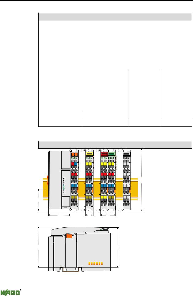
Dimensions |
|
|
|
|
|
01 |
02 |
|
|
|
|
A |
A |
A |
A |
|
A |
|
C |
C |
C |
C |
C |
B |
B |
B |
B |
|
B |
|
D |
D |
D |
D |
D |
24V 0V |
|
|
|
|
|
+ |
+ |
|
|
|
|
|
|
|
|
|
100 |
- |
- |
|
|
|
|
PE |
PE |
|
|
|
|
35 |
|
|
|
|
|
51 |
12 |
|
24 |
|
|
65 |
|
|
|
|
64 |
|
|
|
|
|
|
|
|
|
|
|
|
Seitenansicht Koppler/Controller |
Abmessungen in mm |
||
Fig. 2-12: Dimensions |
g01xx05d |
||
|
|
|
|
|
D R A F T |
WAGO-I/O-SYSTEM 750 |
|
2001-02-27 |
PROFIBUS |
||

Fieldbus coupler / controller |
• 19 |
Fieldbus coupler 750-333 |
|
|
|
3 Fieldbus coupler / controller
3.1 Fieldbus coupler 750-333
This chapter includes:
3.1.1 |
Description...................................................................................... |
21 |
|
3.1.2 |
Hardware......................................................................................... |
22 |
|
3.1.2.1 |
View ......................................................................................... |
22 |
|
3.1.2.2 |
Device supply........................................................................... |
23 |
|
3.1.2.3 |
Fieldbus connection.................................................................. |
24 |
|
3.1.2.4 |
Display elements ...................................................................... |
25 |
|
3.1.2.5 |
Station address ......................................................................... |
26 |
|
3.1.2.6 |
Configuration interface ............................................................ |
26 |
|
3.1.3 |
Operating system............................................................................. |
27 |
|
3.1.4 |
Process image.................................................................................. |
28 |
|
3.1.4.1 |
Local process image ................................................................. |
28 |
|
3.1.4.2 |
Allocation of the input and output data.................................... |
29 |
|
3.1.5 |
Configuration .................................................................................. |
30 |
|
3.1.5.1 |
GSD files.................................................................................. |
31 |
|
3.1.5.2 |
Identification bytes ................................................................... |
32 |
|
3.1.5.3 |
Example.................................................................................... |
34 |
|
3.1.6 |
Parameterising the coupler.............................................................. |
36 |
|
3.1.7 |
Configuring the process data channel ............................................. |
38 |
|
3.1.8 |
Configuration and parameterisation of I/O modules....................... |
39 |
|
3.1.8.1 |
Digital I/O modules.................................................................. |
39 |
|
3.1.8.1.1 |
2 |
DI I/O modules...................................................................... |
39 |
3.1.8.1.2 |
4 |
DI I/O modules...................................................................... |
40 |
3.1.8.1.3 |
2 |
DI I/O modules modules with 1 bit diagn. per channel......... |
41 |
3.1.8.1.4 |
2 |
DO I/O modules .................................................................... |
42 |
3.1.8.1.5 |
2 |
DO I/O modules with 1 bit diagn. per channel...................... |
43 |
3.1.8.1.6 |
2 |
DO I/O module with 2 bit diagn. per channel ....................... |
44 |
3.1.8.1.7 |
4 |
DO I/O modules .................................................................... |
45 |
3.1.8.1.8 |
2 |
DI/DO I/O module with 1 bit diagn. per channel.................. |
46 |
3.1.8.1.9 |
Internal system supply module with diagnosis......................... |
47 |
|
3.1.8.2 |
Analog I/O modules ................................................................. |
48 |
|
3.1.8.2.1 |
2 |
AI I/O modules...................................................................... |
48 |
3.1.8.2.2 |
4 |
AI I/O module ....................................................................... |
49 |
3.1.8.2.3 |
2 |
AO I/O modules .................................................................... |
50 |
3.1.8.3 |
Digital special modules ............................................................ |
51 |
|
3.1.8.3.1 |
Counter modules ...................................................................... |
51 |
|
3.1.8.3.2 |
PWM module ........................................................................... |
52 |
|
3.1.8.4 |
Distance and Angle Messurment Modules............................... |
53 |
|
3.1.8.4.1 |
SSI encoder interface................................................................ |
53 |
|
3.1.8.4.2 |
Incremental encoder interface .................................................. |
54 |
|
3.1.8.4.3 |
Digital impulse interface .......................................................... |
55 |
|
3.1.8.5 |
Serial interfaces ........................................................................ |
56 |
|
3.1.9 |
Diagnosis......................................................................................... |
57 |
|
WAGO-I/O-SYSTEM 750 |
D R A F T |
PROFIBUS |
2001-02-27 |

20 • Fieldbus coupler / controller |
|
|
Fieldbus coupler 750-333 |
|
|
3.1.9.1 |
Station status 1 to 3 .................................................................. |
58 |
3.1.9.2 |
PROFIBUS-DP master address................................................ |
58 |
3.1.9.3 |
Manufacturer‘s identification................................................... |
58 |
3.1.9.4 |
Identification based diagnosis .................................................. |
58 |
3.1.9.5 |
Device status ............................................................................ |
59 |
3.1.9.5.1 |
Internal status messages and arguments ................................... |
60 |
3.1.9.5.2 |
Internal bus status messages and arguments ............................ |
60 |
3.1.9.5.3 |
PROFIBUS-DP status messages and arguments...................... |
61 |
3.1.9.6 |
Channel based diagnosis .......................................................... |
62 |
3.1.9.6.1 |
Fault types of I/O modules with diagnostic capability............. |
63 |
3.1.9.6.2 |
I/O modules fault cases ............................................................ |
64 |
3.1.10 |
LED signalling ................................................................................ |
65 |
3.1.10.1 |
Blink code ................................................................................ |
65 |
3.1.10.2 |
Fieldbus status.......................................................................... |
66 |
3.1.10.3 |
Fault message via blink code of the BUS-LED........................ |
67 |
3.1.10.4 |
Node status ............................................................................... |
68 |
3.1.10.5 |
Fault message via the blink code of the I/O LED..................... |
69 |
3.1.10.6 |
Supply voltage status................................................................ |
70 |
3.1.11 |
Fault behaviour ............................................................................... |
71 |
3.1.11.1 |
Fieldbus failure......................................................................... |
71 |
3.1.11.2 |
Internal bus fault....................................................................... |
72 |
3.1.12 |
Technical data ................................................................................. |
73 |
D R A F T |
WAGO-I/O-SYSTEM 750 |
2001-02-27 |
PROFIBUS |

Fieldbus coupler / controller |
• 21 |
Fieldbus coupler 750-333 |
|
|
|
3.1.1Description
The fieldbus coupler 750-333 displays the peripheral data of all I/O modules in the WAGO-I/O-SYSTEM 750 on PROFIBUS DP.
In the initialisation phase the bus coupler determines the physical structure of the node and creates a process image from this with all inputs and outputs. I/O modules with a bit width smaller than 8 can be combined to form one byte in order to optimise the address space.
In addition the possibility exists to deactivate projected I/O modules. In this manner the physical structure of the node can be individually designed with regard to the peripheral signals, without undertaking any changes to an already existing control application.
The diagnosis concept is based on an identification and channel based diagnosis in accordance with EN 50170. Thus it is not necessary to program modules for the evaluation of manufacturer specific diagnosis information.
•Max. process data length 128 Byte (input and output process image)
•Automatic recognition of transmission speed on the PROFIBUS from
9.6kBd to 12 MBd
•All I/O modules from the WAGO-I/O-SYSTEM 750 are supported
•Configuration modules can be parameterised as wildcards.
•Parameterable substitute value for each channel
•D-Sub 9 pole bus connection
WAGO-I/O-SYSTEM 750 |
D R A F T |
PROFIBUS |
2001-02-27 |